Implement Virtual Networks
- By Dan Patrick, Rick Rainey, Steve Ross, Michael Washam
- 4/10/2018
Skill 4.3: Configure ARM VM Networking
Arguably, VMs are the most widely deployed compute in the Public cloud. Azure provides a very deep and rich set of networking configuration possibilities for VMs. These are important to understand from the perspective of the VM, as many configurations that are possible at the VNet level are also possible at the VM level. In this skill, you will study these configurations. Many configurations are performed at the Network Interface level of VMs including public IP Addresses, private IP Addresses, network security groups, and DNS settings. Others focus more on the use of VMs as Web Servers integrate with VMs along with the Azure load balancer and the App Gateway.
Configure Private Static IP Addresses
VMs in Azure use TCP/IP to communicate with services in Azure, other VMs you have deployed in Azure, on-premises networks, and the internet.
There are two types of IP addresses you can use in Azure:
Public IP addresses Used for communication with the internet
Private IP addresses Used for communication within an Azure virtual network (Vnet), and your on-premises network when you use a VPN Gateway to build a hybrid network
Private IP addresses allow Azure resources to communicate with other resources in a virtual network or an on-premises network through a VPN Gateway or ExpressRoute circuit, without using an internet-reachable IP address.
Using the Azure Resource Manager, a private IP address is associated to the following types of Azure resources:
VM network interfaces
Internal load balancers (ILBs)
Application gateways
Private IP addresses are created with an IPv4 or IPv6 address. VMs cannot communicate between private IPv6 addresses on a Vnet, but can communicate inbound to a private IPv6 address from the internet when using an internet-facing load balancer.
There are two methods used to assign private IP addresses: dynamic or static. The default allocation method is dynamic, where the IP address is automatically allocated from the resource’s subnet (using an Azure DHCP server). This IP address can change when you stop and start the resource.
 EXAM TIP
IPv4 address assignments can be either dynamic or static. Private IPv6 addresses can only be assigned dynamically.
A private IP address is allocated from the subnet’s address range that the network interface is attached to. The address range of the subnet itself is a part of the Virtual Network’s address space.
You can set the allocation method to static to ensure the IP address remains the same. When you specify static, you specify a valid IP address that is part of the resource’s subnet.
Static private IP addresses are commonly used for:
Virtual machines that act as domain controllers or DNS servers
Resources that require firewall rules using IP addresses
Resources accessed by other apps/resources through an IP address
All VMs on a Vnet are assigned a private IP address. If the VM has multiple NICs, a private IP address is assigned to each one. You can specify the allocation method as either dynamic or static for a NIC.
All Azure VMs are assigned Azure Managed DNS servers by default, unless custom DNS servers are assigned. These DNS servers provide internal name resolution for VMs within the same Vnet.
When you create a VM, a mapping for the hostname to its private IP address is added to the Azure DNS servers. If a VM has multiple network interfaces, the hostname is mapped to the private IP address of each NIC. VMs assigned Azure DNS servers can resolve the hostnames of all VMs within the same Vnet to their private IP addresses.
Internal load balancers (ILB) & Application Gateways
Private IP addresses can be assigned to the front-end configuration of an internal load balancer (ILB), or an App Gateway. This IP becomes the internal endpoint, accessible only to the resources within the Vnet, and any remote networks that are connected with the proper network routing in place. You can assign either a dynamic or static private IP address to the front-end configuration.
In Table 4-9, the various resources, their associations, and the type of IP allocation methods (dynamic or static) are captured.
TABLE 4-9 IP allocation methods
| Resource | Association | Supports Dynamic | Support Static |
| Virtual Machine | Network Interface | Yes | Yes |
| Internal load balancer | Front-End Config | Yes | Yes |
| App Gateway | Front-End Config | Yes | Yes |
Enabling static private IP addresses on VMs with the Azure portal
The Network Interface of a VM holds the configurations of the private IP address. This is known as IP Configuration. You can either add new IP Configurations to a NIC or update it from dynamic to static. Using the portal, locate the NIC for the VM that you wish to have a Static IP Address. Once the blade loads for the NIC, click on IP Configurations, then select the IP Configuration you wish to update, as seen in Figure 4-51. Here, you can update the private IP address settings Assignment to be Static, and assign the IP Address. This Address must be within the address range of the subnet where the NIC is located and not currently in use unless you are going to use the address the NIC is already assigned to.
)
FIGURE 4-51 Assigning a Static Private IP Address to a NIC
Enabling static private IP addresses on VMs with PowerShell
When updating an existing NIC to use a static IP address, use two PowerShell cmdlets: Get-AzureRmNetworkInterface and Set-AzureRmNetworkInterface. First, use the Get-AzureRmNetworkInterface to locate the NIC that should be assigned the static IP followed by updating the configuration to be static with its IP address. To save this to Azure, use the Set-AzureRmNetworkInterface cmdlet.
# Update existing NIC to use a Static IP Address and set the IP
$nic=Get-AzureRmNetworkInterface -Name examrefwebvm1892 -ResourceGroupName ExamRefRGPS
$nic.IpConfigurations[0].PrivateIpAllocationMethod = "Static"
$nic.IpConfigurations[0].PrivateIpAddress = "10.0.0.5"
Set-AzureRmNetworkInterface -NetworkInterface $nic
Enabling static private IP addresses on VMs with the Azure CLI
By using the Azure CLI to update a NIC to a static private IP address, use one simple command, az network NIC ip-config with the update argument. Again, the name of the NIC and the resource group are required along with the IP configuration. Remember you are updating the IP configuration properties of the NIC resource.
# Update existing nic to use a Static IP Address and set the IP
az network nic ip-config update --name ipconfig1 --nic-name examrefwebvm1400 --resource-group ExamRefRGCLI --private-ip-address 10.0.1.5
Public IP Address
Public IP addresses allow Azure resources to communicate with internet and public-facing Azure services. Public IP addresses can be created with an IPv4 or IPv6 address. Only internet-facing load balancers can be assigned a Public IPv6 address.
A Public IP address is an Azure Resource that has its own properties, in the same way a VM or VNet is a Resource. Some of the resources you can associate a Public IP address resource with include:
Virtual machine via network interfaces
internet-facing load balancers
VPN Gateways
Application gateways
Like private IP addresses, there are two methods an IP address is allocated to an Azure Public IP address resource: dynamic or static. The default allocation method is dynamic. In fact, an IP address is not allocated at the time the Public IP address resource is created by the Azure fabric.
EXAM TIP
Dynamic Public IP addresses are released when you stop (or delete) the resource. After being released from the resource, the IP address will be assigned to a different resource by Azure. If the IP address is assigned to a different resource while your resource is stopped, once you restart the resource, a different IP address will be assigned. If you wish to retain the IP address, the Public IP address should be changed to static, and that is assigned immediately and never changed.
If you change the allocation method to static, you as the administrator cannot specify the actual IP address assigned to the Public IP address resource. Azure assigns the IP address from a pool of IP addresses in the Azure region where the resource is located.
Static Public IP addresses are commonly used in the following scenarios:
When you must update firewall rules to communicate with your Azure resources.
DNS name resolution, where a change in IP address would require updating host or A records.
Your Azure resources communicate with other apps or services that use an IP address-based security model.
You use SSL certificates linked to an IP address.
One unique property of the Public IP address is the DNS domain name label. This allows you to create a mapping for a configured, fully qualified domain name (FQDN) to your Public IP address. You must provide an Azure globally unique host name that consists of 3-24 alpha-numeric characters, and then Azure adds the domains, creating a FQDN.
EXAM TIP
When you add a DNS Name to your Public IP address, the name will follow this pattern: hostname.region.cloudapp.azure.com. For example, if you create a public IP resource with contosowebvm1 as a DNS Name, and the VM was deployed to a VNet in the Central US region, the fully-qualified domain name (FQDN) of the VM would be: contosowebvm1.centralus.cloudapp.azure.com. This DNS name would resolve on the public internet as well as your VNet to the Public IP address of the resource. You could then use the FQDN to create a custom domain CNAME record pointing to the Public IP address in Azure. If you owned the contoso.com domain, you could create a CNAME record of www.contoso.com to resolve to contosowebvm1.centralus.cloudapp.azure.com. That DNS name would resolve to your Public IP Address assigned by Azure. The client traffic would be directed to the public IP Address associated with that name.
Table 4-10, shows the specific property through which a Public IP address can be associated to a top-level resource and the possible allocation methods (dynamic or static) that can be used.
TABLE 4-10 Public IP Address associations
| Top-level resource | IP Address association | Dynamic | Static |
| Virtual machine | Network interface | Yes | Yes |
| internet-facing load balancer | Front-end configuration | Yes | Yes |
| VPN Gateway | Gateway IP configuration | Yes | No |
| Application gateway | Front-end configuration | Yes | No |
Virtual machines
You can associate a Public IP address with any VM by associating it to its NIC. Public IP addresses, by default, are set to dynamic allocation, but this can be changed to static.
internet-facing Load Balancers
Public IP addresses (either a dynamic or static) can be associated with an Azure load balancer by assigning it to the front-end configuration. The Public IP address then becomes the load balancer’s virtual IP address (VIP). It is possible to assign multiple Public IP addresses to a load balancer front end which enables multi-VIP scenarios like a multi-site environment with SSL-based websites.
VPN Gateways
An Azure VPN Gateway connects an Azure VNet to other Azure VNets or to an on-premises network. A Public IP address is required to be assigned to the VPN Gateway to enable it to communicate with the remote network. You can only assign a dynamic Public IP address to a VPN Gateway.
Application gateways
You can associate a Public IP address with an Azure App Gateway by assigning it to the gateway’s frontend configuration. This Public IP address serves as a load-balanced VIP. You can only assign a dynamic Public IP address to an application gateway frontend configuration.
Creating a Public IP Address using the Azure Portal
Creating a new Public IP Address is a simple process when using the portal. Click New, and then search for Public IP Address in the Marketplace. Like all resources in Azure, some details will be required including the Name of the resource, IP Version, assignment or allocation method, DNS name label, subscription, resource group and location/region. The location is critical, as an IP Address must be in the same location/region as the resource where you want to assign it. Figure 4-52 shows the Azure Create Public IP Address Blade.
)
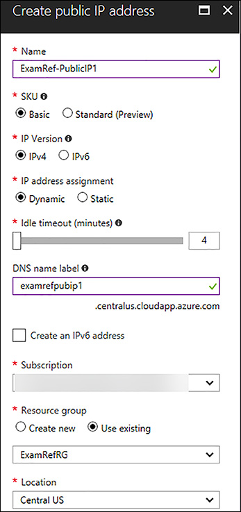
FIGURE 4-52 Creating a Public IP Address in the Azure Portal
Creating a Public IP Address using the PowerShell
When creating a new Public IP address by using PowerShell, the New-AzureRmPublicIpAddress cmdlet is employed. In this script, variables are created for reuse of the code. This command assumes that your resource group is already created.
# Creating a Public IP Address
# Set Variables
$publicIpName = "ExamRef-PublicIP1-PS"
$rgName = "ExamRefRGPS"
$dnsPrefix = "examrefpubip1ps"
$location = "centralus"

# Create the Public IP
New-AzureRmPublicIpAddress -Name $publicIpName `
                           -ResourceGroupName $rgName `
                           -AllocationMethod Static `
                           -DomainNameLabel $dnsPrefix `
                           -Location $location
Creating a Public IP Address using the Azure CLI
When creating a new Public IP address by using the Azure CLI, only one command is required. The command, az network public-ip with the create argument. You need to provide details with respect to the name, resource group, DNS lab, and where it is dynamic or static.
# Creating a Public IP Address
az network public-ip create -g ExamRefRGCLI -n ExamRef-PublicIP1-CLI --dns-name examrefpubip1cli --allocation-method Static
DNS at the Network Interface (NIC) Level
By default, Azure DNS is configured when creating a VM. VMs that are connected to the VNet use this service for name resolution inside the VNet and on the public internet. Along with the resolution of public DNS names, Azure provides internal name resolution for VMs that reside within the same VNet. Within a VNet, the DNS suffix is consistent, so the FQDN is not needed. This means that VMs on the same VNet using the Azure DNS Server can connect directly via their host names.
Just as it is possible to configure your own Customer Managed DNS Servers for a VNet, this configuration is also possible at the NlC level. When using your own DNS servers, Azure provides the ability to specify multiple DNS servers per NIC.
The DNS Servers configuration for a Network Interface on a VM can be completed using the Azure portal, PowerShell or Azure CLI.
Configure DNS Settings on Network Interfaces using the Azure Portal
To configure the DNS Servers on a Network Interface using the Azure portal, open the NIC associated with the VM requiring the custom settings, as seen in Figure 4-53. Next, click on the DNS Servers link in the Settings menu. You can then enter the DNS Servers you wish for this VM to use. In the example, the two DNS Servers are well known, and they are publicly available on the internet but different than the VNet.
)
FIGURE 4-53 Custom DNS Servers for Network Interface configured using the Portal
Configure DNS Settings on Network Interfaces using the PowerShell
When creating a new VNet, you can specify the DNS Configure the DNS Servers using PowerShell. The Set-AzureRmNetworkInterface along with the Get-AzureRmNetworkInterface cmdlets will be used together to make the change to an existing Network Interface. The first line of PowerShell will get the existing interface and its configurations followed by using the Clear and Add Methods that will update the PowerShell pipeline with new configuration that will be passed to the Set-AzureRmNetworkInterface to update and save to the Network Interface. The DnsSettings.DnsServers.Clear() method is first used to clear out the current configuration no matter what is there. Then the DnsSettings.DnsServers.Add (“dns-server-ip-address”) will be used to input the IPs that should be used by the Network Interface.
$nic = Get-AzureRmNetworkInterface `
            -ResourceGroupName "ExamRefRG" `
            -Name "examrefwebvm172"
$nic.DnsSettings.DnsServers.Clear()
$nic.DnsSettings.DnsServers.Add("8.8.8.8")
$nic.DnsSettings.DnsServers.Add("4.2.2.1")
$nic | Set-AzureRmNetworkInterface
EXAM TIP
When you change your VNet settings to point to your customer provided DNS servers on its network interfaces, you must restart VMs for the new settings to be assigned to the VM’s operating system. When the VM reboots it re-acquires its IP address and the new DNS settings are in place.
Configure DNS Settings on Network Interfaces using the Azure CLI
To update an existing a Network Interface using the Azure CLI as well as specify custom DNS Servers add the --dns-servers argument when using the az network nic update command. The first command will revert the settings to the default servers. Just as in the PowerShell example, we want to remove the current settings back to default first, so you know exactly what the settings are on the Network Interface. If you only run the second command, your DNS Servers will be added to the bottom of the existing list if there are already custom settings on the Network Interface.
az network nic update -g ExamRefRG -n examrefwebvm172 --dns-servers ""
az network nic update -g ExamRefRG -n examrefwebvm172 --dns-servers 8.8.8.8 4.2.2.1
EXAM TIP
DNS Servers specified for a Network Interface take precedence over those specified for the VNet. This means if you want specific machines on your VNet, use a different DNS Server, you can assign this at the NIC level, and the VNet DNS Server setting will be ignored by that VM.
Network Security Groups (NSGs)
A network security group (NSG) is a networking filter containing a list of security rules that when applied will allow or deny network traffic to resources connected to Azure VNets. These rules can manage both inbound and outbound Traffic. NSGs can be associated to subnets, individual Network Interfaces attached to ARM VMs, and Classic VMs.
In this section, you will learn how to configure NSGs on Network Interfaces and are associated with VMs in Azure Resource Manager. The process of filtering network traffic via a NSG on a NIC is multi-step. First, the network security group must be created. Next, the desired rules would need to be created in that NSG. Once these two steps are completed it will then be associated with the NIC.
EXAM TIP
NSGs that are associated to network interfaces are said to be filtering “East/West” traffic.
Creating an NSG and Associating with a NIC using the Azure Portal
To create a NSG to be associated with a NIC in the portal click New, followed by Networking and then, select network security group. Once the Create network security group blade loads, provide a Name, the Subscription where your resources are located, the resource group for the NSG and the Location (this must be the same as the resources you wish to apply to the NSG).
In Figure 4-54, the NSG will be created to allow HTTP traffic on Port 80 into a NIC of a VM named ExamRefWEBVM1. The name of the NSG is ExamRefWEBVM1-nsg located in the same resource group ExamRefRG.
)
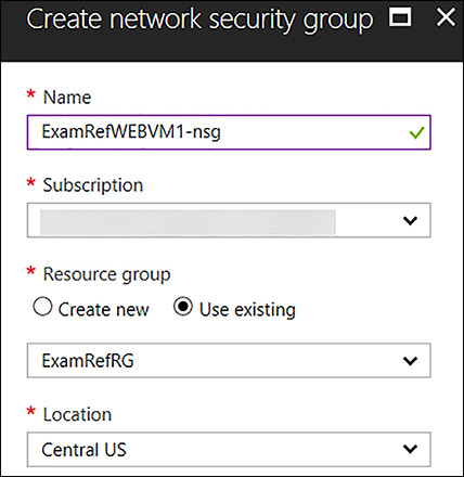
FIGURE 4-54 Creating an NSG that is associated with a VM NIC
Once the ExamRefWEBVM1-nsg has been created, the portal will open the Overview blade. Here, you will see the NSG has been created, but there are no inbound or outbound security rules beyond the default rules.
To create the inbound rule to allow port 80 select Inbound Security Rules followed by +Add. For the Add inbound security rule, update using the following details, as seen in Figure 4-55:
Source Any
Source port ranges *
Destination Any
Destinations port ranges 80
Protocol Any
Action Allow
Priority 100
Name PORT_HTTP_80
Description All HTTP
)
FIGURE 4-55 An Inbound Rule to Allow traffic on Port 80 is created
Once the portal has configured the inbound rule, it will appear in the portal. Review your rule to ensure it has been created correctly. Now, this NSG with its default rules and newly created inbound rule named Port_80_HTTP is currently not filtering any traffic since it has yet to be associated with NIC. In Figure 4-56, you see the NIC of ExamRefWEBVM1 being selected after selecting Network Interfaces under Settings, followed by selecting +Associate. The portal will ask you to select the NIC name associated with ExamRefWEBVM1. The NSG will immediately start filtering traffic.
)
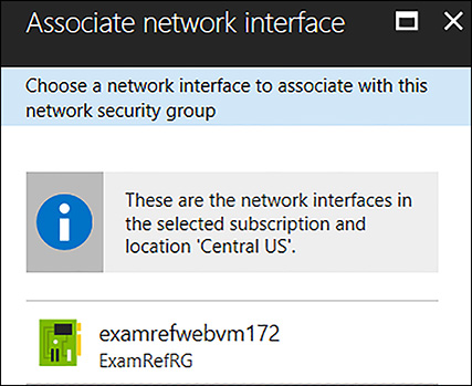
FIGURE 4-56 Associating the NSG with the NIC of the VM
Upon association of the NSG with the NIC, TCP traffic on Port 80 will be allowed to this VM. Of course, you would need to have a webserver VM configured and listening on Port 80 to respond, but with this NSG, the ability is now opened for that traffic to flow to the VMs.
Creating an NSG and Associating with a Subnet using PowerShell
To create a NSG and configure the rules using PowerShell, use the New-AzureRmNetworkSecurityRuleConfig and New-AzureRmNetworkSecurityGroup PowerShell cmdlets together. In this example, it’s assumed you have run the Login-AzureRmAccount command as well as created a resource group and the VNet from the earlier example using PowerShell. The NSG will be created to allow HTTP traffic on Port 80 into a NIC of a VM named ExamRefWEBVM1. The name of the NSG is ExamRefWEBVM1-nsg located in the same resource group ExamRefRGPS.
#Build a new Inbound Rule to Allow TCP Traffic on Port 80 to the Subnet
$rule1 = New-AzureRmNetworkSecurityRuleConfig -Name PORT_HTTP_80 `
                                              -Description "Allow HTTP" `
                                              -Access Allow `
                                              -Protocol Tcp `
                                              -Direction Inbound `
                                              -Priority 100 `
                                              -SourceAddressPrefix * `
                                              -SourcePortRange * `
                                              -DestinationAddressPrefix 10.0.0.0/24 `
                                              -DestinationPortRange 80

#Create a new Network Security Group and add the HTTP Rule
$nsg = New-AzureRmNetworkSecurityGroup -ResourceGroupName ExamRefRGPS `
                                       -Location centralus `
                                       -Name "ExamRefWEBVM1-nsg" `
                                       -SecurityRules $rule1
After the NSG is created, along with the inbound rule, next you need to associate this with the NIC to control the flow of network traffic by using this filter. To achieve this goal, use Get-AzureRmNetworkInterface. After the configuration on the NIC has been set, use Set-AzureRmNetworkInterface to save the configuration to the NIC.
#Associate the Rule with the NIC from ExamRefWEBVM1
$nic = Get-AzureRmNetworkInterface -ResourceGroupName ExamRefRGPS -Name examrefwebvm1892
$nic.NetworkSecurityGroup = $nsg
Set-AzureRmNetworkInterface -NetworkInterface $nic
Creating an NSG and Associating with a NIC using the Azure CLI
Creating an NSG by using the CLI is a multi-step process, just as it is with the portal and PowerShell. The az network nsg create command is first used to create the NSG. After the NSG is created, next create the rule to allow Port 80 to the subnet. This is created by using the az network nsg rule create command. After the rule has been created, this is associated with the NIC of a VM named ExamRefWEBVM1 by using the az network nic update command. The name of the NSG is ExamRefWEBVM1-nsg, located in the same resource group ExamRefRGCLI.
# Create the NSG
az network nsg create --resource-group ExamRefRGCLI --name ExamRefWEBVM1-nsg

# Create the NSG Inbound Rule allowing TCP traffic on Port 80
az network nsg rule create --resource-group ExamRefRGCLI --name PORT_HTTP_80
--nsg-name ExamRefWEBVM1-nsg --direction Inbound --priority 100 --access Allow
--source-address-prefix "*" --source-port-range "*" --destination-address-prefix
"*" --destination-port-range "80" --description "Allow HTTP" --protocol TCP

# Associate the NSG with the NIC from ExamRefWEBVM1
az network nic update --resource-group ExamRefRGCLI --name examrefwebvm1400
 --network-security-group ExamRefWEBVM1-nsg
User Defined Routes (UDR) with IP Forwarding
User Defined Routes (UDR) allow for changing the default system routes that Azure creates for you in an Azure VNet. The UDRs forward traffic to a virtual appliance such as a firewall. For that traffic to be allowed to pass to that virtual appliance, you must enable IP forwarding on the network interface of the VM.
A virtual appliance is nothing more than a VM that runs an application used to handle network traffic in some way. By default, VMs in Azure do not have the ability to forward packets that are intended for a different destination, so this configuration allows those packets to flow through the device. Of course, the firewall device would have to be configured as well by using its internal tools to pass this traffic. This configuration doesn’t typically involve any changes to the Azure UDR or VNet.
IP forwarding can be enabled on a network interface by using the Azure portal, PowerShell, or the Azure CLI. In Figure 4-57, you see that the network interface of the NGFW1 VM has the IP forwarding set as Enabled. This VM is now able to accept and send packets that were not originally intended for this VM.
)
FIGURE 4-57 IP Forwarding Enabled on a Virtual Appliance
External and Internal load balancing with HTTP and TCP health probes
The Azure load balancer provides the means for you to deliver highly available and high performing web based applications using your VMs running in a VNet. This is a Layer 4 (TCP, UDP) load balancer that distributes inbound traffic among healthy instances of services defined in a load-balanced set.
The load balancer can run in three different configurations:
Load balance incoming internet traffic to VMs. This configuration is known as internet-facing load balancing.
Traffic between virtual machines in a VNet is also supported. These can be between virtual machines in cloud services, or between on-premises computers and virtual machines in a cross-premises Virtual Network. This is known as internal load balancing.
Forward external traffic to a specific virtual machine, which is a means of using Network Address Translation (NAT).
The load balancer uses a hash-based distribution algorithm. Like most load balancers, it uses a 5-tuple hash composed of source IP, source port, destination IP, destination port, and protocol type to map traffic to available servers, by default. This provides stickiness within a transport session, meaning that packets in the same TCP or UDP session are directed to the same instance behind the load-balanced endpoint. If, or when, the client closes and reopens the connection or starts a new session from the same source IP, the source port changes.
You have control over how inbound communication comes into your endpoints, known as the input endpoint. An input endpoint listens on a public port and forwards traffic to an internal port. You can map the same ports for an internal or external endpoint or use a different port for them.
For example, you can have a web server configured to listen to port 81 while the public endpoint mapping is port 80. The creation of a public endpoint triggers the creation of a load balancer instance.
Health Probes
At its core, the purpose of a load balancer is twofold: to spread traffic across a farm of VMs that are providing a service so you don’t overload them and to ensure that the VMs are healthy and ready to accept traffic.
The Azure load balancer can probe the health of your VMs deployed into a VNet. When a VM probe experiences a failure, this means that the VM is no longer able to provide the service, therefore the load balancer marks it as an unhealthy instance and stops sending new connections to the VM. Existing connections are not impacted by being removed from the pool of healthy instances, but users could experience failures if they have current open connections to that VM.
The Azure load balancer supports two types of probes for virtual machines:
TCP Probe This probe relies on a successful TCP session establishment to a defined probe port. If the VM responds to the request to establish a simple TCP connection on the port defined when creating the probe, the VM is marked as healthy. For example, a TCP probe could be created connecting to portal 80. If the machine is active and allows connections on port 80, the load balancer would be able to connect and the machine would pass the probe. If for some reason the machine was stopped or the load balancer could no longer connect to port 80, it would be marked as unhealthy.
HTTP Probe This probe is used to determine if a VM is serving webpages without issues by using the HTTP protocol. When a webpage loads successfully, there is an HTTP error code that is given: 200. This error code means that the page loaded successfully. One of the configurations on the HTTP probe is the path to the file used for the probe which by default, is marked a “/”. This tells the Azure load balancer to load the default webpage from the VM. Often this would be default.aspx or index.html, but you can configure this if you want to create your own page to check the health of a site. Just returning the default page with 200 doesn’t provide deeper insight as to the true functionally of your site, so using some custom logic to determine the health of the site could make sense. A developer would create a custom page and then you would configure the load balancer to load that page. If it loads correctly, the 200 is provided and the VM is put into the pool of available VMs to service client requests.
EXAM TIP
For both TCP and HTTP probes you can configure the interval and the unhealthy threshold. The interval is the amount of time between the probe attempts, or in other words how often Azure uses this probe. Unhealthy threshold is the number of consecutive failures that must occur before the VM is considered unhealthy.
Creating the Azure load balancer using the Azure portal
To use the Azure load balancer, the administrator must first provision the resource including the Frontend IP configuration. After this step has been completed then you will need to create the backend pool, heath probes, and load balancing rules.
To create the load balancer in the portal, select New, followed by Networking and locate the load balancer. As seen in Figure 4-58, supply a name for the load balancer, assign a type of Public or Internal, select a public or private IP Address, along with the subscription, resource group, and location. In the case of the example, an internet facing load balancer will be created with a public IP Address, and it will point to two Web Servers named ExamRefWEBVM1 and ExamRefWEBVM2 that are part of an Availability Set called ExamRefWebAVSet. Both VMs have one NIC that is connected to the Apps subnet of the ExamRefVNET VNet.
)
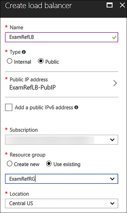
FIGURE 4-58 Creating a Load Balancer with the Azure portal
After the load balancer has been created, execute the next steps to integrate your VMs with the load balancer:
Backend Pool
Health Probe HTTP
Load Balancing Rule
Figure 4-59 shows the portal to add a backend pool. To create the backend pool, open the load balancer in the portal and then in the Settings section, click Backend pools. Next click +Add Provide a Name for the Backend Pool, leave the IPv4 section for the IP Version and move to the Associated to drop-down. Select Availability Set and another drop-down appears. Select ExamRefWebAVSet from the drop-down list. Next click the +Add a target network IP configuration. Next a Target virtual machine drop-down appears and you can select ExamRefWEBVM1 along with its network IP configuration. Click +Add a target network IP configuration again and follow this same procedure to select ExamRefWEBVM2. After you complete adding both VMs, click OK.
)
FIGURE 4-59 Creating the Backend pool which exposes the VMs
To ensure your Web Servers are ready, you will need to add the HTTP Probe. To begin configuring the HTTP probe, select the Health probe link in Settings and then +Add. As seen in Figure 4-60, provide a Name, select the HTTP protocol, and accept the defaults of Port 80, Interval of 5 and Unhealth threshold of 2. Then click OK. Notice that there is an additional item named path which is the location of a file or folder on the web server for the load balancer to connect.
)
FIGURE 4-60 Creating a HTTP Health Probe
Now that you have created the backend pool telling the load balancer which machines are to be used, and you have configured the probes to help determine which ones are healthy, you will now put it all together with the load balancing rules. These rules help to bring these configurations together connecting the Frontend to the Backend. To create the rule, click the load balancing rules link under settings, and then select +Add. Complete the following configurations, as seen in Figure 4-61:
Name ExamRefLBRule
IP Version IPv4
Frontend IP Address Select the Public IP Address
Protocol TCP
Port 80
Backend port 80
Backend pool Select the Pool you created
Heath Probe Select the TCP Rule
Session Persistence None
Idle Timeout 4 minutes
Floating IP Disabled
)
FIGURE 4-61 Creating the Load Balancing Rule using the Backend Pool and Health Probe
After this is put in the place, if the VMs added to the backend pool are configured with a web server and there are no network security groups or other firewalls blocking port 80, you should be able to connect to the Public IP address of the load balancer and see the webpage.
Creating the Azure Load Balancer using PowerShell
When creating a new load balancer by using PowerShell, there are quite a few steps involved. The script must first create a Public IP address, the front IP configuration, backend pool, and the HTTP probe. Then, the load balancer rule is followed by the load balancer resource where these other configurations will be put in place. After you create the load balancer, update the backend pool referencing the NICs of the VMs that are serving the website. The PowerShell cmdlets used for this script include:
New-AzureRmPublicIpAddress
New-AzureRmLoadBalancerFrontendIpConfig
New-AzureRmLoadBalancerBackendAddressPoolConfig
New-AzureRmLoadBalancerProbeConfig
New-AzureRmLoadBalancer
Get-AzureRmVirtualNetwork
Get-AzureRmVirtualNetworkSubnetConfig
Get-AzureRmNetworkInterface
Set-AzureRmNetworkInterfaceIpConfig
Set-AzureRmNetworkInterface
In this example, an internet facing load balancer will be created with a public IP Address, and it will point to two Web Servers named ExamRefWEBVM1 and ExamRefWEBVM2, and they are part of an Availability Set called ExamRefWebAVSet. Both VMs have one NIC connected to the Apps subnet of the ExamRefVNET-PS VNet created in earlier steps.
# Set Variables
$publicIpName = "ExamRefLB-PublicIP-PS"
$rgName = "ExamRefRGPS"
$dnsPrefix = "examreflbps"
$location = "centralus"
$lbname = "ExamRefLBPS"
$vnetName = "ExamRefVNET-PS"

# Create the Public IP
$publicIP = New-AzureRmPublicIpAddress -Name $publicIpName `
                           -ResourceGroupName $rgName `
                           -AllocationMethod Static `
                           -DomainNameLabel $dnsPrefix `
                           -Location $location

#Create Frontend IP Configuration
$frontendIP = New-AzureRmLoadBalancerFrontendIpConfig -Name ExamRefFrontEndPS `
                                                      -PublicIpAddress $publicIP

# Create Backend Pool
$beAddressPool = New-AzureRmLoadBalancerBackendAddressPoolConfig -Name ExamRefBackEndPoolPS

#Create HTTP Probe
$healthProbe = New-AzureRmLoadBalancerProbeConfig -Name HealthProbe `
                                                  -RequestPath '/' `
                                                  -Protocol http `
                                                  -Port 80 `
                                                  -IntervalInSeconds 5 `
                                                  -ProbeCount 2

#Create Load Balancer Rule
$lbrule = New-AzureRmLoadBalancerRuleConfig -Name ExamRefRuleHTTPPS `
                                            -FrontendIpConfiguration $frontendIP `
                                            -BackendAddressPool  $beAddressPool `
                                            -Probe $healthProbe `
                                            -Protocol Tcp `
                                            -FrontendPort 80 `
                                            -BackendPort 80

#Create Load Balancer
New-AzureRmLoadBalancer -ResourceGroupName $rgName `
                        -Name $lbName `
                        -Location $location `
                        -FrontendIpConfiguration $frontendIP `
                        -LoadBalancingRule $lbrule `
                        -BackendAddressPool $beAddressPool `
                        -Probe $healthProbe

# Add the Web Servers to the Backend Pool
$vnet = Get-AzureRmVirtualNetwork -Name $vnetName `
                                  -ResourceGroupName $rgName
$subnet = Get-AzureRmVirtualNetworkSubnetConfig -Name Apps `
                                                -VirtualNetwork $vnet
$nic1 = Get-AzureRmNetworkInterface -Name examrefwebvm1480 `
                                    -ResourceGroupName $rgName
$nic1 | Set-AzureRmNetworkInterfaceIpConfig -Name ipconfig1 `
                                            -LoadBalancerBackendAddressPool
                                            $beAddressPool `
                                            -Subnet $subnet
$nic1 | Set-AzureRmNetworkInterface

$nic2 = Get-AzureRmNetworkInterface -Name examrefwebvm2217 `
                                    -ResourceGroupName $rgName
$nic2 | Set-AzureRmNetworkInterfaceIpConfig -Name ipconfig1 `
                                            -LoadBalancerBackendAddressPool
                                            $beAddressPool `
                                            -Subnet $subnet
$nic2 | Set-AzureRmNetworkInterface
Creating the Azure load balancer using the Azure CLI
The same configurations are required when creating a load balancer by using the Azure CLI as they are when creating load balancers in the portal or PowerShell. The process using CLI is not quite as intricate as the process using PowerShell though. You can leverage the az network lb command with a few different arguments along with the az network public-ip to create the Public IP address.
# Creating a Public IP Address
az network public-ip create -g ExamRefRGCLI -n ExamRefLB-PublicIP-CLI --dns-name
 examreflbcli --allocation-method Static

#Create Load Balancer
az network lb create -n ExamRefLBCLI -g ExamRefRGCLI -l centralus --backend-pool-name
 ExamRefBackEndPoolCLI --frontend-ip-name ExamRefFrontEndCLI --public-ip-address
 ExamRefLB-PublicIP-CLI

#Create HTTP Probe
az network lb probe create -n HealthProbe -g ExamRefRGCLI --lb-name ExamRefLBCLI
--protocol http --port 80 --path / --interval 5 --threshold 2

#Create Load Balancer Rule
az network lb rule create -n ExamRefRuleHTTPCLI -g ExamRefRGCLI --lb-name
ExamRefLBCLI --protocol Tcp --frontend-port 80 --backend-port 80
--frontend-ip-name ExamRefFrontEndCLI --backend-pool-name ExamRefBackEndPoolCLI
 --probe-name HealthProbe

# Add the Web Servers to the Backend Pool
az network nic ip-config address-pool add --address-pool ExamRefBackEndPoolCLI
 --lb-name ExamRefLBCLI -g ExamRefRGCLI --nic-name examrefwebvm160 --ip-config-name
 ipconfig1
az network nic ip-config address-pool add --address-pool ExamRefBackEndPoolCLI
--lb-name ExamRefLBCLI -g ExamRefRGCLI --nic-name examrefwebvm2139 --ip-config-name
 ipconfig1
Direct Server Return
Some application scenarios require the same port to be used on the frontend configuration and the backend on the VMs. Common examples of port reuse include clustering for high availability, network virtual appliances, and exposing multiple TLS endpoints without re-encryption.
If you want to reuse the backend port across multiple rules, you must enable Floating IP in the load balancer rule definition. Floating IP is a portion of what is known as Direct Server Return (DSR). In Azure, this ability is typically only used for deploying SQL Server Always On Availability Groups. This is a clustering technology for providing highly available databases using Azure VMs. Microsoft recommends only using this feature when configuring SQL Always On Availability Groups Listener. This can only be configured with creating a load balancing rule and the frontend port must match the backend port. Figure 4-62 shows a SQL Always on Listener with the direct server return set to Enabled.
)
FIGURE 4-62 SQL Always on Listener with the Direct Server Return Enabled
This functionality should only be used if the VM that is responding as a part of the backend pool is connecting directly to a VM within the VNet or networks that are connected to the VNet. It is not supported to use direct server return with clients that are on the internet. This is due to the server talking back directly to the client rather than its traffic going through the load balancer back to the client.
Design and Implement Application Gateway (App Gateway)
The Application Gateway can be deployed as a Layer 7 load balancer into a VNet. VMs that are a part of the VNet can then be added as the backend pool of an App Gateway. These VMs host the application, much like the Azure load balancer being added to the backend pool is a part of the NIC IP configuration. This can be accomplished by using the Azure portal, PowerShell, and the Azure CLI.
Configure VMs as Backend Pool for App Gateway using the Azure Portal
To configure the VMs as part of the Backend pool using the Azure portal open the App Gateway and then select backend pools under the Settings section. Next, click on the name of the Backend pool created when the App Gateway was provisioned. Then, select +Add target followed by VM. From there, you can select the first VM and its IP Configuration. In the case of this example, the ExamRefWEBVM1 and ExamRefWEBVM2 have been selected with ipconfig1 from each VM. Notice their private IP address is listed, as this is the IP Address the App Gateway will use when directing traffic to the VMs. Once they have been added click Save and the App Gateway will update. Figure 4-63 shows the appGatewayBackendPool with the VMs configurations added.
)
FIGURE 4-63 App Gateway Backend Pool with two VMs added
After the portal reports that the App Gateway update is complete, you can connect to the Public IP address of the App Gateway by using your web browser. It does take a few minutes for the sites to come online, so be patient.
Configure VMs as Backend Pool for App Gateway using the PowerShell
To update the backend pool of the App Gateway with the VMs you will use a combination of the Get-AzureRmApplicationGateway cmdlet along with the with the Get-AzureRmApplicationGatewayBackendAddressPool and Get-AzureRmNetworkInterface. These cmdlets will be used to load information about the various resources into variables that can then be used with the Set-AzureRmApplicationGatewayBackendAddressPool cmdlet to configure the backend pool with the addresses of your web servers. These backend pool members are all validated to be healthy by probes, whether they are basic probes or custom probes. Traffic is then routed to them when requests come into the application gateway. Backend pools can be used by multiple rules within the application gateway. This means one backend pool could be used for multiple web applications that reside on the same host.
# Add VM IP Addresses to the Backend Pool of App Gateway
$appGw = Get-AzureRmApplicationGateway -Name "ExamRefAppGWPS" -ResourceGroupName
 "ExamRefRGPS"
$backendPool = Get-AzureRmApplicationGatewayBackendAddressPool -Name
 "appGatewayBackendPool" -ApplicationGateway $AppGw
$nic01 = Get-AzureRmNetworkInterface -Name "examrefwebvm1480" -ResourceGroupName
"ExamRefRGPS"
$nic02 = Get-AzureRmNetworkInterface -Name "examrefwebvm2217" -ResourceGroupName
"ExamRefRGPS"
Set-AzureRmApplicationGatewayBackendAddressPool -ApplicationGateway $appGw `
                          -Name $backendPool `
                          -BackendIPAddresses
$nic01.IpConfigurations[0].PrivateIpAddress,$nic02.IpConfigurations[0].PrivateIpAddress
Configure VMs as Backend Pool for App Gateway using the Azure CLI
Only one command is required to update the backend pool of the App Gateway using the Azure CLI. The az network application-gateway address-pool is used, but you must know the IP Addresses of the VM’s IP Configurations to make this work properly.
# Add VM IP Addresses to the Backend Pool of App Gateway
az network application-gateway address-pool update -n appGatewayBackendPool
--gateway-name ExamRefAppGWCLI -g ExamRefRGCLI --servers 10.0.0.6 10.0.0.7