Implement Virtual Networks
- By Dan Patrick, Rick Rainey, Steve Ross, Michael Washam
- 4/10/2018
In this sample chapter from Exam Ref 70-533 Implementing Microsoft Azure Infrastructure Solutions, 2nd Edition, take a deep dive in virtual networking and the skills needed to configure, design, and implement them.
Azure Virtual Networks (VNet) provide the infrastructure for deploying workloads that require an advanced network configuration. VNets provide support for hybrid network connectivity from Azure to either your on-premises network or to other VNets within Azure regions. The use of VMs in Azure is entirely dependent upon the VNets where deployed. These can be internet-facing applications that are deployed behind either the Azure load balancer for Layer 4 workloads, or the Azure Application Gateway, which can deploy more complex Layer 7 implementations. Azure VNets also provide support for deploying intranet or n-tier workloads using the internal load balancer. Workloads, such as Active Directory, are also enabled in the cloud using features only supported in VNets (such as subnets and static IP addresses). This chapter will focus on VNets as well as how to create and configure them. There is also a focus on key hybrid technologies.
Skills covered in this chapter
Skill 4.1 Configure Virtual Networks
Skill 4.2 Design and implement multi-site or hybrid network connectivity
Skill 4.3 Configure ARM VM Networking
Skill 4.4 Design and implement a communication strategy
Skill 4.1: Configure Virtual Networks
Configuring an Azure VNet involves network design skills such as specifying the address spaces (IP network ranges), and dividing the network into subnets. Setting up name resolution with DNS at the Virtual Network level is critical when connecting multiple networks together, and VNet peering is one option for this that is covered here. Securing VNets by implementing network security groups, along with the ability to control the routing on VNets applying User Defined Routes, is also covered. These serve as the most important tasks for deployment of VMs into VNets to provide services for your cloud implementation. One such deployment of VMs will be the use of the Azure Application Gateway used for Layer 7 load balancing. Customization of these many services, along with designing the VNet itself, is covered in this skill.
Create a Virtual Network (VNet)
Azure VNets enable you to securely connect Azure VMs to each other and to extend your on-premises network to the Azure cloud. A VNet is a representation of your own network in the cloud and is a logical isolation of the Azure cloud dedicated to your subscription.
VNets are isolated from one another allowing you to create separate VNets for development, testing, and production. Although it’s not recommended, you can even use the same Classless Inter-Domain Routing (CIDR) address blocks. The best plan is to create multiple VNets that use different CIDR address blocks. This allows you to connect these networks together if you wish. Each VNet can be segmented into multiple subnets. Azure provides internal name resolution for VMs and cloud service role instances connected to a VNet. You can optionally configure a VNet to use your own DNS servers instead of using Azure internal name resolution.
The following are some of the connectivity capabilities that you should understand about VNets:
internet connectivity All Azure Virtual Machines (VMs), connected to a VNet, have access to the internet by default. You can also enable inbound access to specific resources running in a VNet, such as a web server.
Azure resource connectivity Azure resources such as VMs can be connected to the same VNet. The VMs can connect to each other by using private IP addresses, even if they are in different subnets. Azure provides system routes between subnets, VNets, and on-premises networks, so you don’t have to configure and manage routes.
VNet connectivity VNets can be connected together, enabling VMs connected to any VNet to communicate with any VM on any other VNet. This can be accomplished by using VNet peering if they are in the same region or by using VPN Gateways if they are in different Azure regions. Traffic from one VNet to another VNet is always secured and never egresses to the internet.
On-premises connectivity VNets can be connected to on-premises networks through private network connections and Azure (ExpressRoute), or through an encrypted Site-to-Site VPN connection over the internet.
Traffic filtering (firewall) VM network traffic can be filtered by using 5-tuple inbound and outbound by source IP address and port, destination IP address and port, and protocol.
Routing You can optionally override Azure’s default routing by configuring your own routes, or by using BGP routes through a VPN Gateway.
All VMs connected to a VNet have outbound connectivity to the internet by default. The resource’s private IP address is source network address translated (SNAT), to a Public IP address by the Azure infrastructure. You can change the default connectivity by implementing custom routing and traffic filtering.
To communicate inbound to Azure resources from the internet, or to communicate outbound to the internet without SNAT, a resource must be assigned a Public IP address.
Azure VNets can be created by using the Azure portal, Azure PowerShell cmdlets, or the Azure CLI.
Creating a Virtual Network using the Azure Portal
To create a new VNet by using the Azure portal, first click New and then select Networking. Next, click Virtual Network as shown in Figure 4-1.
)
FIGURE 4-1 Creating a Virtual Network using the Azure Portal
The Create Virtual Network blade opens. Here you can provide configuration information about the Virtual Network. This blade requires the following inputs, as shown in Figure 4-2:
)
Name of the Virtual Network
Address Space to be used for the VNet using CIDR notation
Subscription in which the VNet is created
The resource group where the VNet is created
Location for VNet
Subnet Name for the first subnet in the VNet
The Address Range of the first Subnet
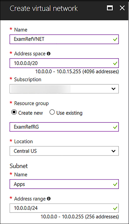
FIGURE 4-2 Create Virtual Network Blade
The address space is the most critical configuration for a VNet in Azure. This is the IP range for the entire network that will be divided into subnets. The address space can almost be any IP range that you wish (public or private). You can add multiple address spaces to a VNet. To ensure this VNet can be connected to other networks, the address space should never overlap with any other networks in your environment. If a VNet has an address space that overlaps with another Azure VNet or on-premises network, the networks cannot be connected, as the routing of traffic will not work properly.
These include the following:
224.0.0.0/4 (Multicast)
255.255.255.255/32 (Broadcast)
127.0.0.0/8 (Loopback)
169.254.0.0/16 (Link-local)
168.63.129.16/32 (Internal DNS)
10.0.0.0 - 10.255.255.255 (10.0.0.0/8)
172.16.0.0 - 172.31.255.255 (172.16.0.0/12)
192.168.0.0 - 192.168.255.255 (192.168.0.0/16)
Once the VNet has completed provisioning, you can review the settings using the Azure portal. Notice the Apps subnet has been created as part of the inputs you made as seen in Figure 4-3.
)
FIGURE 4-3 Virtual Network created using the Azure portal
To create another subnet in the ExamRefVNET, click +Subnet on this blade and provide the following inputs, as shown in Figure 4-4:
Name of the Subnet: Data.
Address Range: This is the portion of the address space that is made available for the subnet. In the case, it is 10.0.1.0/24.
)
FIGURE 4-4 Virtual Network created using the Azure Portal with two subnets Apps and Data
Creating a Virtual Network with PowerShell
Using the Azure PowerShell cmdlets, you can create and configure VNets programmatically. Let’s walk through how to create a VNet using PowerShell.
Before you can create or manage any resources in your Azure subscription by using the Azure PowerShell cmdlets, you must log in by executing the Login-AzureRmAccount cmdlet.
Login-AzureRmAccount
Once the PowerShell session is authenticated to Azure, the first thing needed will be a new resource group. Using the New-AzureRmResourceGroup cmdlet, you can create a new resource group. This cmdlet requires you to specify the resource group name as well as the name of the Azure region. These values are defined in the variables $rgName and $location.
$rgName     = "ExamRefRGPS"
$location   = "Central US"
New-AzureRmResourceGroup -Name $rgName -Location $location
If you wanted to use an existing resource group you can use the Get-AzureRmResourceGroup cmdlet to see if the resource group. You can also use the Get-AzureRmLocation cmdlet to view the list of available regions.
In the code example below, the New-AzureRmVirtualNetworkSubnetConfig cmdlet is used to create two local objects that represent two subnets in the VNet. The VNet is subsequently created with the call to New-AzureRmVirtualNetwork. It is passed the address space of 10.0.0.0/16. You could also pass in multiple address spaces like how the subnets were passed in using an array. Notice how $subnets = @() creates an array and then the array is loaded with two different commands using the New-AzureRmVirtualNetworkSubnetConfig cmdlet. When the New-AzureRmVirtualNetwork cmdlet is called in the last command of the script, the two subnets are then populated by the array values that have been loaded in the $subnets.
$subnets = @()
$subnet1Name = "Apps"
$subnet2Name = "Data"
$subnet1AddressPrefix = "10.0.0.0/24"
$subnet2AddressPrefix = "10.0.1.0/24"
$vnetAddresssSpace = "10.0.0.0/16"
$VNETName = "ExamRefVNET-PS"
$rgName = "ExamRefRGPS"
$location = "Central US"
$subnets = New-AzureRmVirtualNetworkSubnetConfig -Name $subnet1Name `
                                    -AddressPrefix $subnet1AddressPrefix
$subnets = New-AzureRmVirtualNetworkSubnetConfig -Name $subnet2Name `
                                    -AddressPrefix $subnet2AddressPrefix
$vnet = New-AzureRmVirtualNetwork -Name $VNETName `
                          -ResourceGroupName $rgName `
                          -Location $location `
                          -AddressPrefix $vnetAddresssSpace `
                          -Subnet $subnets
Following the completion of the PowerShell script, there should be a new resource group and a new VNet provisioned. In Figure 4-5, you see the VNet ExamRefVNET-PS was created in the ExamRefRGPS resource group. You can now click on the subnets button to view the new App and Data subnets and their address ranges.
)
FIGURE 4-5 Virtual Network created using PowerShell
Creating a Virtual Network using the Azure CLI
By using the Azure CLI 2.0, you can create and configure VNets by using individual commands or as a part of a script to be run using a bash script or batch file depending upon the platform (bash is supported on Linux, macOS, or Windows Subsystem for Linux).
In this case here, let’s walk through each command to create the VNet using the Azure CLI Cloud Shell. To initiate the Azure CLI Cloud Shell, open the Azure portal and then click the CLI symbol along the upper right-hand corner as seen in Figure 4-6.
)
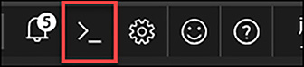
FIGURE 4-6 Azure CLI Cloud Shell
After a few moments, the Cloud Shell will be ready, and you will see an interactive bash prompt. In Figure 4-7, Azure Cloud Shell is ready to use with your subscription.
)
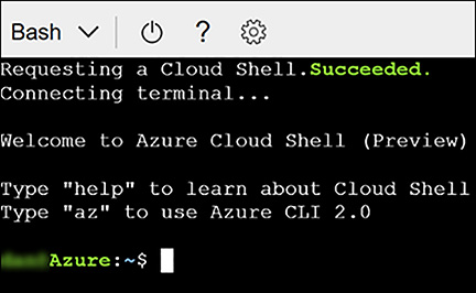
FIGURE 4-7 Azure CLI Cloud Shell
The first step will be creating a new resource group for the VNet using the Azure CLI. This will be accomplished using the az group create command. You will need to specify a location for the resource group. To locate a list of regions that are available for your subscription, you can use the command az account list-locations.
az group create -n ExamRefRGCLI -l "centralus"
Next, you can create the new VNet using the az network vnet create command.
az network vnet create --resource-group ExamRefRGCLI -n ExamRefVNET-CLI
--address-prefixes 10.0.0.0/16 -l "centralus"
Then, following the creation of the VNet, create the App and Data subnets. This is accomplished using the az network vnet subnet create command. You will run these commands one at a time for each subnet.
az network vnet subnet create --resource-group ExamRefRGCLI --vnet-name
ExamRefVNET-CLI -n Apps --address-prefix 10.0.1.0/24
az network vnet subnet create --resource-group ExamRefRGCLI --vnet-name
ExamRefVNET-CLI -n Data --address-prefix 10.0.2.0/24
After running these commands there should be a new resource group named ExamRefRGCLI and the newly provisioned VNet named ExamRefVNET-CLI. In Figure 4-8, you see the ExamREFVNET-CLI, which was created in the ExamRefRGCLI resource group. If you click the Subnets button you will see the new App and Data subnets with the address ranges from the commands entered.
)

FIGURE 4-8 Virtual Network created using the Azure CLI Cloud Shell
Design subnets
A subnet is a child resource of a VNet, which defines segments of address spaces within a VNets. These are created using CIDR blocks of the address space that was defined for the VNet. NICs can be added to subnets and connected to VMs. This will provide connectivity for various workloads.
The name of a subnet must be unique within that VNet. You cannot change the subnet name subnet following its creation. During the creation of a VNet while using the Azure portal, the requirement is for you to define one subnet, even though a VNet isn’t required to have any subnets. In the portal, you can define only one subnet when you create a VNet. You can add more subnets to the VNet later after it has been created. You can create a VNet that has multiple subnets by using Azure CLI or PowerShell.
When creating a subnet, the address range must be defined. The address range of the new subnet must be within the address space you assigned for the VNet. The range that is entered will determine the number of IP Addresses that are part of the subnet.
 EXAM TIP
Azure will hold back a total of 5 IP Addresses for every subnet that is created in a VNet. Azure reserves the first and last IP addresses in each subnet like standard IP networks with one for the network identification and the other for broadcast. Azure also holds three additional addresses for internal use starting from the first address in the subnet. For example, if the CIDR range of a subnet has its first IP as .0 then the first useable IP would be .4. So, if the address range was 192.168.1.0/24 then 192.168.1.4 would be the first address assigned to a NIC. Also, the smallest subnet on an Azure VNet would be a CIDR /29. This would provide 3 useable IP Addresses and 5 IP Addresses that Azure would use.
Subnets provide the ability to isolate network traffic between various types of workloads. These are often different types of servers or even tiers of applications. Examples of this could include separating traffic bound for web servers and database servers. These logical segmentations allow for clean separations, so they can be secured and managed. This allows for very precise application of rules securing data traffic as well as how traffic flows into and out of a given set of VMs.
In Azure, the security rules are applied using network security groups, and the traffic flows are controlled using route tables. Designing the subnets should be completed upfront and should be considered while determining the address space. Remember that for each subnet, Azure holds back 5 IP Addresses. If you create a VNet with 10 subnets, you are losing 50 IP addresses to Azure. Careful up-front planning is critical to not causing yourself a shortage of IPs later.
Changes to subnets and address ranges can only be made if there are no devices connected to the subnet. If you wish to make a change to a subnet’s address range, you would first have to delete all the objects in that subnet. If the subnet is empty, you can change the range of addresses to any range that is within the address space of the VNet not assigned to any other subnets.
Subnets can be only be deleted from VNets if they are empty. Once a subnet is deleted, the addresses that were part of that address range would be released and available again for use within new subnets that you could create.
Subnets have the following properties: Name, Location, Address range, Network security group, Route table and Users. Table 4-1 discusses each of these properties.
TABLE 4-1 Properties of a Virtual Network Subnet
| Property | Description |
| Name | Subnet name up to 80 characters. May contain letters, numbers, underscores, periods, or hyphens. Must start with a letter or number. Must end with a letter, number, or underscore. |
| Location | Azure location must be the same as the Virtual Network. |
| Address Range | Single address prefix that makes up the subnet in CIDR notation. Must be a single CIDR block that is part of one of the VNets address spaces. |
| Network Security Group | NSGs are essentially firewall rules that can be associated to a subnet. These rules are then applied to all NICs that are attached to that subnet. |
| Route Table | Route table applied to the subnet that would change the default system routes. These are used to send traffic to destination networks that are different than the routes that Azure uses by default. |
| Users | Which users have access to use the subnet as a part of Role-Based Access Control. |
EXAM TIP
Network security groups (NSGs) can be associated to subnets, individual NICs or both. NSGs associated with subnets will enforce their inbound or outbound rules to all NICs that are connected to the subnet. Inbound rules from a subnet NSG will apply first as packets entering the subnet prior to entering the NIC. Upon enforcement following the NSG in association with the subnet, any NSGs associated with NICs would then be enforced. The opposite is true for outbound rules with the NIC NSG being enforced followed by the subnet NSG, as the traffic is following in the reverse direction. For example, if a VM was running a web server on PORT 80, and it has a NSG associated to the NIC with an inbound Rule that allowed traffic on PORT 80, and the subnet did not, the packets would be discarded without ever reaching the VM. The reason is because the NSG at the subnet level is blocking the traffic on PORT 80 for all NICs.
Gateway subnets
The basis for deploying hybrid clouds is the connection of an on-premises network along with an Azure VNet. This configuration allows clients and servers deployed in Azure to communicate with those in your datacenter and network. To deploy this type of connection, a VPN Gateway needs to be created in Azure. All VPN Gateways must be placed into a special gateway subnet.
The gateway subnet contains the IP addresses the VPN Gateway VMs and services will use. When you create your VPN Gateway, special Azure managed VMs are deployed to the gateway subnet, and they are configured with the required VPN Gateway settings. Only the VPN Gateways should be deployed to the gateway subnet and its name must be “GatewaySubnet” to work properly.
When you create the gateway subnet, you are required to specify the number of IP addresses available using an address range. The IP addresses in the gateway subnet will be allocated to the gateway VMs and services. It’s important to plan ahead because some configurations require more IP addresses than others. For example, if you plan on using ExpressRoute and a Site to Site VPN as a failover, you will need more than just two IPs. You can create a gateway subnet as small as /29, but it’s Microsoft’s recommendation to create a gateway subnet of /28 or larger (i.e., /28, /27, /26). That way, if you add functionality in the future, you won’t have to tear down your gateway. Just delete and recreate the gateway subnet to allow for more IP addresses.
Creating a GatewaySubnet using the Azure portal
The GatewaySubnet can be created using the Azure portal, PowerShell or CLI. Because these aren’t created very often they are typically created using the Azure portal.
To create the GatewaySubnet, first open an existing VNet, and move to the subnets under settings. From here, the current subnets can be reviewed. Click +GatewaySubnet, and you will be required to enter the address range for the subnet as seen in Figure 4-9.
)
FIGURE 4-9 Adding a GatewaySubnet used for VPN Gateways
Once the Gateway subnet is added, the VPN Gateway can be created and placed into this subnet. Many network administrators will create this address range much further away from their subnets in terms of the IP Addressing. Figure 4-10 shows, the GatewaySubnet created using a CIDR block of 10.0.100.0/28. The other subnets are using /24 CIDR blocks for Apps and Data. In this case the GatewaySubnet is 98 subnets away from the others. This is not required, as the GatewaySubnet could be any CIDR address range belonging to the address space of the VNet. This would provide for a continuation of the subnet scheme put in place if the admin wanted to build additional subnets. The next logical subnet would be in the 10.0.2.0/24 and so forth as more are created.
)
FIGURE 4-10 GatewaySubnet after being created using the Azure Portal
Setup DNS at the Virtual Network level
The Domain Naming Service (DNS) is critical on all modern networks, and VNets are no different. It is possible for all network communication to be completed by using IP addresses, but it is much simpler to use names that can easily be remembered and do not change. There are two options for providing DNS services to a VNet:
Azure Provided DNS Highly durable and scalable service
Customer Managed DNS Build and deploy your own DNS Servers
By default, Azure DNS is configured when creating a VNet. VMs connected to the VNet use this service for name resolution inside the VNet, as well as on the public internet. Along with resolution of public DNS names, Azure provides internal name resolution for VMs that reside within the same VNet. Within a VNet the DNS suffix is consistent, so the Fully Qualified Domain Name (FQDN), is not needed. This means that VMs on the same VNet using the Azure DNS Server can connect directly via their host names.
Although Azure-provided name resolution does not require any configuration, it is not the appropriate choice for all deployment scenarios. If your needs go beyond what Azure provided DNS can provide, you will need to implement your own Customer Managed DNS Servers. Table 4-2 captures the recommended DNS infrastructure based on various common requirements. Focus in on the scenarios that would require you to deploy your own DNS.
TABLE 4-2 Determining a DNS strategy for an Azure Virtual Network
| Requirement | Recommended DNS infrastructure |
| Name resolution between role instances or VMs located in the same cloud service or VNet | Azure provided DNS |
| Name resolution between role instances or VMs located in different VNets | Customer managed DNS |
| Resolution of on-premises computer and service names from role instances or VMs in Azure | Customer managed DNS |
| Resolution of Azure hostnames from on-premises computers | Customer managed DNS |
| Reverse DNS for internal IPs | Customer managed DNS |
When using your own DNS servers, Azure provides the ability to specify multiple DNS servers per VNet. Once in place, this configuration will cause the Azure VMs in the VNet to use your DNS servers for name resolution services. You must restart the VMs for this configuration to update.
You can alter the DNS Servers configuration for a VNet using the Azure portal, PowerShell or Azure CLI.
Configuring VNet Custom DNS Settings using the Azure portal
To configure the DNS Servers using the Azure portal, open the VNet that will be configured and click DNS Servers, as seen in Figure 4-11. Select Custom and then input the IP Addresses of your DNS Servers that have been configured and click Save.
)
FIGURE 4-11 Custom DNS Servers configured using the Azure Portal
Configuring VNet Custom DNS Settings using PowerShell
When creating a new VNet, you can specify the customer DNS settings configuration using PowerShell. The New-AzureRmVirtualNetwork cmdlet with the -DNSServer (as a part of the command) will create a new VNet with the DNS Servers already specified. This command would assume that your resource group was already created.
$subnets = @()
$subnet1Name = "Apps"
$subnet2Name = "Data"
$subnet1AddressPrefix = "10.0.0.0/24"
$subnet2AddressPrefix = "10.0.1.0/24"
$vnetAddresssSpace = "10.0.0.0/16"
$VNETName = "ExamRefVNET-PS"
$rgName = "ExamRefRGPS"
$location = "Central US"

$subnets = New-AzureRmVirtualNetworkSubnetConfig -Name $subnet1Name `
                                    -AddressPrefix $subnet1AddressPrefix
$subnets = New-AzureRmVirtualNetworkSubnetConfig -Name $subnet2Name `
                                    -AddressPrefix $subnet2AddressPrefix
$vnet = New-AzureRmVirtualNetwork -Name $VNETName `
                                  -ResourceGroupName $rgName `
                                  -Location $location `
                                  -AddressPrefix $vnetAddresssSpace `
                                  -DNSServer 10.0.0.4,10.0.0.5 `
                                  -Subnet $subnet
Configuring VNet Custom DNS settings using the Azure CLI
To create a VNet using the Azure CLI and specify custom DNS Servers, you will need to add the —dns-servers argument when using both az network vnet create commands.
az network vnet create --resource-group ExamRefRGCLI -n ExamRefVNET-CLI
--address-prefixes 10.0.0.0/16 --dns-servers 10.0.0.4 10.0.0.5 -l "centralus"
Customer-managed DNS servers within a VNet can forward DNS queries to Azure’s recursive resolvers to resolve hostnames within that VNet. For example, you could use a Domain Controller (DC), running in Azure to respond to DNS queries for its domains, and forward all other queries to Azure. This allows your VMs to see both on-premises resources (via the DC), and Azure-provided hostnames (via the forwarder). Access to Azure’s recursive resolvers is provided via the virtual IP 168.63.129.16. If you promote a Domain Controller that is running as VM in Azure, it will automatically pick up the Azure DNS resolver as a Forwarder. In Figure 4-12, you see a Domain Controller deployed to an Azure VNet acting as a DNS Server for that VNet. The Forwarder is set to the address of the Azure recursive resolver.
)
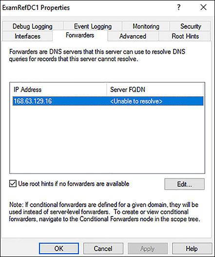
FIGURE 4-12 DNS Forwarder configuration on a Domain Controller running in a Virtual Network
User Defined Routes (UDRs)
Azure VMs that are added to a VNet can communicate with each other over the network automatically. Even if they are in different subnets or attempting to gain access to the internet, there are no configurations required by you as the administrator. Unlike typical networking, you will not need to specify a network gateway, even though the VMs are in different subnets. This is also the case for communication from the VMs to your on-premises network when a hybrid connection from Azure to your datacenter has been established.
This ease of setup is made possible by what is known as system routes. System routes define how IP traffic flows in Azure VNets. The following are the default system routes that Azure will use and provide for you:
Within the same subnet
Subnet to another subnet within a VNet
VMs to the internet
A VNet to another VNet through a VPN Gateway
A VNet to another VNet through VNet peering (Service Chaining)
A VNet to your on-premises network through a VPN Gateway
)
FIGURE 4-13 N-Tier Application Deployed to Azure VNet using system routes
Figure 4-13 shows an example of how these system routes make it easy to get up and running. System routes provide for most typical scenarios by default, but there are use cases where you will want to control the routing of packets.
One of the scenarios is when you want to send traffic through a virtual appliance such as a third-party load balancer, firewall or router deployed into your VNet from the Azure Marketplace.
To make this possible, you must create User Defined Routes (UDRs). These UDRs specify the next hop for packets flowing to a specific subnet through your appliance instead of following the system routes. As seen in Figure 4-14, by using the UDR, traffic will be routed through the device to the destination.
)
FIGURE 4-14 N-Tier Application Deployed with a Firewall using User Defined Routes
EXAM TIP
You can have multiple route tables, and the same route table can be associated to one or more subnets. Each subnet can only be associated to a single route table. All VMs in a subnet use the route table associated to that subnet.
Figure 4-15 shows a UDR that has been created to allow for traffic to be directed to a virtual appliance. In this case, it would be a Firewall running as a VM in Azure in the DMZ subnet.
)
FIGURE 4-15 User Defined Route forcing network traffic through firewall
Connect VNets using VNet peering
VNet peering allows you to connect two Azure Resource Manager (ARM), VNets located in the same region together without complex integration. The peered VNets must have non-overlapping IP address spaces. The address spaces in either VNet cannot be added to or deleted from a VNet once a VNet is peered with another VNet.
Once peered, the VNets appear as one network and all VMs in the peered VNets can communicate with each other directly. The traffic between VMs is routed through the Microsoft backbone network in the same way that traffic is routed between the VM in the same VNet through private IP addresses.
You can create a VNet peering using the Azure portal, PowerShell or Azure CLI. Figure 4-16 shows VNETA and VNETB, and they are both in the North Central Azure region. These two VNets will be used to describe how to create VNet peerings.
)
FIGURE 4-16 VNet peering between two networks in the North Central Region
Creating a VNet peering using the Azure portal
The VNets you wish to peer must already be created to establish a VNet peering. To create a new VNet peering from VNETA to VNETB as shown in Figure 4-17, connect to the Azure portal and locate VNETA. Once this is located under Settings, click peerings, and then select +Add. This will load the Add peering blade. Use the following inputs to connect a standard VNet peering:
)
Name VNETA-to-VNETB
Peer Details Resource Manager (leave the I Know My Resource ID unchecked)
Subscription Select the Subscription for VNETB
Virtual Network Choose VNETB
Configuration Enabled (leave the remaining three boxes unchecked for this simple VNet Peering)
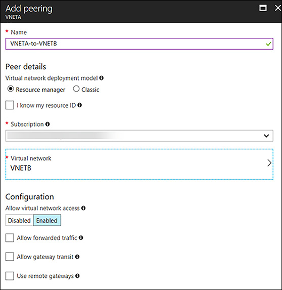
FIGURE 4-17 Adding peering from VNETA to VNETB using the Portal
Once this process has been completed, the VNet peering will appear in the portal along with the initiation of peering status, as seen in Figure 4-18. To complete the VNet peering, you will follow the same steps on VNETB.
)
FIGURE 4-18 VNETA-to-VNETB Peering showing as Initiated in the Azure Portal
Now, in the portal, complete the same steps using VNETB. Open VNETB in the Azure portal and click peerings. Next, click +Add and complete the Add peering blade by using the following inputs, as shown in Figure 4-19:
Name VNETB-to-VNETA
Peer Details Resource Manager (Leave the I Know My Resource ID checkbox unchecked)
Subscription Select the Subscription for VNETA
Virtual Network Choose VNETA
Configuration Enabled (leave the other three boxes unchecked for this simple peering)
)
FIGURE 4-19 Adding peering from VNETB to VNETA using the Portal
Once the portal has completed the provisioning of the VNet Peering, it will appear in the peering of VNETB and show as Connected with a peer of VNETA, as seen in Figure 4-20. Now the two VNets: VNETA and VNETB are peers, and VMs on these networks can see each other. They are accessible, as if this was one Virtual Network.
)
FIGURE 4-20 VNETB-to-VNETA Peering showing as Connected in the Azure Portal
In Figure 4-21, the peering blade of VNETA shows the peering status VNETA-to-VNETB is also as Connected to VNETB.
)
FIGURE 4-21 VNETA-to-VNETB Peering showing as Connected in the Azure Portal
Creating a VNet peering using PowerShell
When creating a new VNet peering using PowerShell, you will first leverage the Get-AzureRmVirtualNetwork cmdlet to assign information about the VNETA and VNETB into two variables. Using the Add-AzureRmVirtualNetworkPeering, create the VNet peerings on both VNets just as you did in the portal. Upon completion, the VNet peering will provision, and move to a connected peering status. You can use the Get-AzureRmVirtualNetworkPeering cmdlet to verify the peering status of the VNets.
# Load VNETA and VNETB into Variables
$vneta = Get-AzureRmVirtualNetwork `
-Name "VNETA" `
-ResourceGroupName "VNETARG"

$vnetb = Get-AzureRmVirtualNetwork `
-Name "VNETB" `
-ResourceGroupName "VNETBRG"

# Peer VNETA to VNETB.
Add-AzureRmVirtualNetworkPeering `
  -Name 'VNETA-to-VNETB' `
  -VirtualNetwork $vneta `
  -RemoteVirtualNetworkId $vnetb.Id

# Peer VNETB to VNETA.
Add-AzureRmVirtualNetworkPeering `
  -Name 'VNETA-to-VNETB'
  -VirtualNetwork $vnetb `
  -RemoteVirtualNetworkId $vneta.Id

#Check on the Peering Status
  Get-AzureRmVirtualNetworkPeering `
  -ResourceGroupName VNETARG `
  -VirtualNetworkName VNETA `
  | Format-Table VirtualNetworkName, PeeringState
Creating VNet Peering using the Azure CLI
To create a VNet peering using the Azure CLI, you will need to use the az network vnet show command to get the Resource ID of each VNet. Next, you will use the az network vnet peering create command to create each of the VNet peerings. Upon successfully running these commands, you can use the az network vnet peering list command to see the peering status as Connected.
# Get the Resource IDs for VNETA and VNETB.
az network vnet show --resource-group VNETAResourceGroupName --name VNETA
--query id --out tsv
az network vnet show --resource-group VNETBResourceGroupName --name VNETB
 --query id --out tsv

# Peer VNETB to VNET: the output from the Command to find the Resource ID
 for VNETA & VNETB is used with the --remote-vnet-id argument
az network vnet peering create --name VNETA-to-VNETB --resource-group VNETARG
 --vnet-name VNETA --allow-vnet-access --remote-vnet-id /subscriptions/
11111111-1111-1111-1111-111111111111/resourceGroups/VNETBRG/
providers/Microsoft.Network/virtualNetworks/VNETB

# Peer VNETB to VNETA. the output from the Command to find the Resource ID for
 VNETA is used with the --remote-vnet-id argument
az network vnet peering create --name VNETB-to-VNETA --resource-group
VNETBRG --vnet-name VNETB --allow-vnet-access --remote-vnet-id /subscriptions/
11111111-1111-1111-1111-111111111111/resourceGroups/VNETARG/providers/
Microsoft.Network/virtualNetworks/VNETA

#To See the Current State of the Peering
az network vnet peering list --resource-group VNETARG --vnet-name VNETA -o table
Setup Network Security Groups (NSGs)
A network security group (NSG) is a networking filter (firewall) containing a list of security rules, which when applied allow or deny network traffic to resources connected to Azure VNets. These rules can manage both inbound and outbound traffic. NSGs can be associated to subnets and/or individual network interfaces attached to ARM VMs and to classic VMs. Each NSG has the following properties regardless of where it is associated:
NSG Name
Azure region where the NSG is located
Resource group
Rules that define whether inbound or outbound traffic is allowed or denied
EXAM TIP
When an NSG is associated to a subnet, the rules apply to all resources connected to the subnet. Traffic can further be restricted by also associating an NSG to a VM or NIC. NSGs that are associated to subnets are said to be filtering “North/South” traffic, meaning packets flow into and out of a subnet. NSGs that are associated to network interfaces are said to be filtering “East/West” traffic, or how the VMs within the subnet connect to each other.
NSG Rules
NSG Rules are the mechanism defining traffic the administrator is looking to control. Table 4-3 captures the important information to understand about NSG Rules.
TABLE 4-3 NSG properties
| PROPERTY | DESCRIPTION | CONSTRAINTS | CONSIDERATIONS |
| Name | Name of the rule | Must be unique within the region. Must end with a letter, number, or underscore. Cannot exceed 80 characters. |
You can have several rules within an NSG, so make sure you follow a naming convention that allows you to identify the function of your rule. |
| Protocol | Protocol to match for the rule | TCP, UDP, or * | Using * as a protocol includes ICMP (East-West traffic only), as well as UDP and TCP, can reduce the number of rules you need. This is a very broad approach, so it’s recommended that you only use when necessary. |
| Source port range | Source port range to match for the rule | Single port number from 1 to 65535, port range (example: 1-65535), or * (for all ports) | Source ports could be ephemeral. Unless your client program is using a specific port, use * in most cases. Try to use port ranges as much as possible to avoid the need for multiple rules. Multiple ports or port ranges cannot be grouped by a comma. |
| Destination port range | Destination port range to match for the rule | Single port number from 1 to 65535, port range (example: 1-65535), or * (for all ports) | Try to use port ranges as much as possible to avoid the need for multiple rules. Multiple ports or port ranges cannot be grouped by a comma. |
| Source address prefix | Source address prefix or tag to match for the rule | Single IP address (example: 10.10.10.10), IP subnet (example: 192.168.1.0/24), Tag or * (for all addresses) | Consider using ranges, default tags, and * to reduce the number of rules. |
| Destination address prefix | Destination address prefix or tag to match for the rule | Single IP address (example: 10.10.10.10), IP subnet (example: 192.168.1.0/24), Tag or * (for all addresses) | Consider using ranges, default tags, and * to reduce the number of rules. |
| Direction | Direction of traffic to match for the rule | Inbound or outbound | Inbound and outbound rules are processed separately, based on direction. |
| Priority | Rules are checked in the order of priority. Once a rule applies, no more rules are tested for matching. | Unique Number between 100 and 4096. Uniqueness is only within this NSG. | Consider creating rules jumping priorities by 100 for each rule to leave space for new rules you might create in the future. |
| Access | Type of access to apply if the rule matches | Allow or deny | Keep in mind that if an allow rule is not found for a packet, the packet is dropped. |
Default Rules
All NSGs have a set of default rules, as shown in Table 4-5 and Table 4-6. These default rules cannot be deleted, but since they have the lowest possible priority, they can be overridden by the rules that you create. The lower the number, the sooner it will take precedence.
The default rules allow and disallow traffic as follows:
Virtual network Traffic originating and ending in a Virtual Network is allowed both in inbound and outbound directions.
internet Outbound traffic is allowed, but inbound traffic is blocked.
Load balancer Allow Azure’s load balancer to probe the health of your VMs and role instances. If you are not using a load balanced set, you can override this rule.
TABLE 4-5 Default Inbound Rules
| Name | Priority | Source IP | Source Port | Destination IP | Protocol | Access |
| AllowVNetInBound | 65000 | VirtualNetwork | * | VirtualNetwork | * | Allow |
| AllowAzureLoad BalancerInBound |
65001 | AzureLoadBalancer | * | * | * | Allow |
| DenyAllInBound | 65500 | * | * | * | * | Deny |
TABLE 4-6 Default Outbound Rules
| Name | Priority | Source IP | Source Port | Destination IP | Protocol | Access |
| AllowVNetOutBound | 65000 | VirtualNetwork | * | VirtualNetwork | * | Allow |
| AllowinternetOutBound | 65001 | * | * | internet | * | Allow |
| DenyAllOutBound | 65500 | * | * | * | * | Deny |
EXAM TIP
NSG Rules are enforced based on their Priority. Priority values start from 100 and go to 4096. Rules will be read and enforced starting with 100 then 101, 102 etc., until all rules have been evaluated in this order. Rules with the priority “closest” to 100 will be enforced first. For example, if you had an inbound rule that allowed TCP traffic on Port 80 with a priority of 250 and another that denied TCP traffic on Port 80 with a priority of 125, the NSG rule of deny would be put in place. This is because the “deny rule”, with a priority of 125 is closer to 100 than the “allow rule”, containing a priority of 250.
Default Tags
Default tags are system-provided identifiers to address a category of IP addresses. You can use default tags in the source address prefix and destination address prefix properties of any rule.
There are three default tags you can use:
VirtualNetwork (Resource Manager) (VIRTUAL_NETWORK for classic) This tag includes the Virtual Network address space (CIDR ranges defined in Azure) all connected on-premises address spaces and connected Azure VNets (local networks).
AzureLoadBalancer (Resource Manager) (AZURE_LOADBALANCER for classic) This tag denotes Azure’s infrastructure load balancer. The tag translates to an Azure datacenter IP where Azure’s health probes originate.
internet (Resource Manager) (INTERNET for classic) This tag denotes the IP address space that is outside the Virtual Network and reachable by public internet. The range includes the Azure owned public IP space.
Associating NSGs
NSGs are used to define the rules of how traffic is filtered for your IaaS deployments in Azure. NSGs by themselves are not implemented until they are “associated”, with a resource in Azure. NSGs can be associated to ARM network interfaces (NIC), which are associated to the VMs, or subnets.
For NICs associated to VMs, the rules are applied to all traffic to/from that Network Interface where it is associated. It is possible to have a multi-NIC VM, and you can associate the same or different NSG to each Network Interface. When NSGs are applied to subnets, rules are applied to traffic to/from all resources connect to that subnet.
EXAM TIP
Understanding the effective rules of NSGs is critical for the exam. Security rules are applied to the traffic by priority in each NSG in the following order:
NSG applied to subnet If a subnet NSG has a matching rule to deny traffic, the packet is dropped.
NSG applied to NIC If VM\NIC NSG has a matching rule that denies traffic, packets are dropped at the VM\NIC, even if a subnet NSG has a matching rule that allows traffic.
Outbound traffic:
NSG applied to NIC If a VM\NIC NSG has a matching rule that denies traffic, packets are dropped.
NSG applied to subnet If a subnet NSG has a matching rule that denies traffic, packets are dropped, even if a VM\NIC NSG has a matching rule that allows traffic.
Configuring and Associating NSGs with Subnets
NSGs are a bit different than other types of resources in Azure given they are first created. You must add rules to them (inbound or outbound), and they must be associated to have the desired effect of filtering traffic based on those rules. Remember that NSGs with no rules will have the six default rules covered earlier in this section.
NSGs can be configured and associated with subnets using the Azure portal, PowerShell or the Azure CLI.
Creating an NSG and associating with a subnet using the Azure portal
To create a NSG using the portal, first click New, then Networking, and select network security group. Once the Create Network Security Group blade loads you will need to provide a Name, the Subscription where your resources are located, the resource group for the NSG and the Location (this must be the same as the resources you wish to apply the NSG). In Figure 4-22, the NSG will be created to allow HTTP traffic into the Apps subnet and be named AppsNSG.
)
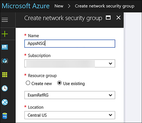
FIGURE 4-22 Creating a Network Security Group using the Azure Portal
After AppsNSG is created, the portal opens the Overview blade. Here, you see that the NSG has been created, but there are no inbound or outbound security rules beyond the default rules. In Figure 4-23, the Inbound Security Rules blade of the AppsNSG is shown.
)
FIGURE 4-23 The Inbound Security Rules showing only the Default Rules
The next step is to create the inbound rule for HTTP. Under the settings area, click on Inbound Security Rules link. The next step will be to click +Add to allow HTTP traffic on Port 80 into the Apps subnet. In the Add inbound security rule blade, configure the following items, and click OK as seen in Figure 4-24.
Source Any
Source Port Ranges *
Destination IP Addresses
Destination IP Addresses/CIDR Ranges The Apps Subnet: 10.0.0.0/24
Destination Port Ranges 80
Protocol TCP
Action Allow
Priority 100
Name Port 80_HTTP
)
FIGURE 4-24 Adding an Inbound Rule to allow HTTP traffic
Once the portal is saved the inbound rule, it will appear in the portal. Review your rule to ensure it has been created correctly. This NSG with its default rules and the newly created inbound rule named Port_80_HTTP are not filtering any traffic. It has yet to be associated with a subnet or a Network Interface, so the rules are currently not in effect. The next task will be to associate it with the Apps subnet. In the Azure portal / Settings, click subnets button, and click +Associate. The portal will ask for two configurations: “Name of the Virtual Network” and the “Name of the subnet”. In Figure 4-25, the VNet ExamRefVNET and subnet Apps has been selected.
)
FIGURE 4-25 The AppsNSG has been associated with the Apps Subnet
After being saved, the rules of the NSG are now being enforced for all network interfaces that are associated with this subnet. This means that TCP traffic on Port 80 is allowed for all VMs that are connected to this subnet. Of course, you need to have a webserver VM configured and listening on Port 80 to respond, but with this NSG, you have opened the ability for Port 80 traffic to flow to the VMs in this subnet from any other subnet in the world.
Creating an NSG and associating with a subnet using PowerShell
To create an NSG and configure the rules by using PowerShell, you need to use the New-AzureRmNetworkSecurityRuleConfig and New-AzureRmNetworkSecurityGroup PowerShell cmdlets together. In this example, it’s assumed that you have run the Login-AzureRmAccount command and have already created a resource group and the Vnet (created from the earlier example of creating a Vnet by using PowerShell).
#Build a new Inbound Rule to Allow TCP Traffic on Port 80 to the Subnet
$rule1 = New-AzureRmNetworkSecurityRuleConfig –Name PORT_HTTP_80 `
                                              -Description "Allow HTTP" `
                                              -Access Allow `
                                              -Protocol Tcp `
                                              -Direction Inbound `
                                              -Priority 100 `
                                              -SourceAddressPrefix * `
                                              -SourcePortRange * `
                                              -DestinationAddressPrefix 10.0.0.0/24 `
                                              -DestinationPortRange 80
$nsg = New-AzureRmNetworkSecurityGroup –ResourceGroupName ExamRefRGPS `
                                       -Location centralus `
                                       -Name "AppsNSG" `
                                       -SecurityRules $rule1
After the NSG has been created along with the inbound rule, next you need to associate this with the subnet to control the flow of network traffic using this filter. To achieve this goal, you need to use Get-AzureRmVirtualNetwork and the Set-AzureRmVirtualNetworkSubnetConfig. After the configuration on the subnet has been set, use Set-AzureRmVirtualNetwork to save the configuration in Azure.
#Associate the Rule with the Subnet Apps in the Virtual Network ExamRefVNET-PS
$vnet = Get-AzureRmVirtualNetwork –ResourceGroupName ExamRefRGPS –Name ExamRefVNET-PS

Set-AzureRmVirtualNetworkSubnetConfig –VirtualNetwork $vnet `
                                      -Name Apps `
                                      -AddressPrefix 10.0.0.0/24 `
                                      -NetworkSecurityGroup $nsg
Set-AzureRmVirtualNetwork –VirtualNetwork $vnet
Creating an NSG and associating with a subnet using the Azure CLI
Creating a NSG using the CLI is a multi-step process just as it was with the portal and PowerShell. The az network nsg create command will first be used to create the NSG. Upon creation of the NSG, will be the rule where we will again allow Port 80 to the subnet. This is created using the az network nsg rule create command. Upon creation, this will be associated with the Apps subnet on the VNet using the az network vnet subnet update command.
# Create the NSG

az network nsg create --resource-group ExamRefRGCLI --name AppsNSG

# Create the NSG Inbound Rule allowing TCP traffic on Port 80

az network nsg rule create --resource-group ExamRefRGCLI --name PORT_HTTP_80
--nsg-name AppsNSG --direction Inbound --priority 100 --access Allow
--source-address-prefix "*" --source-port-range "*" --destination-address-prefix "*"
 --destination-port-range "80" --description "Allow HTTP" --protocol TCP

# Associate the NSG with the ExamRefVNET-CLI Apps Subnet

az network vnet subnet update --resource-group ExamRefRGCLI
--vnet-name ExamRefVNET-CLI --name Apps --network-security-group AppsNSG
Deploy a VM into a Virtual Network
VMs can only be deployed into Virtual Networks. VNets provide the networking capabilities that make it possible to benefit from the services of the VM you deploy. The Azure portal allows you to create a VM in an existing Virtual Network, requiring you to specify the subnet. Another option is to create a new VNet while you are creating the new VM.
After a VM is deployed into a VNet, it cannot be moved to another VNet (without deleting it and re-creating), so it is important to consider carefully which VNet the VM should be deployed to during creation.
When creating a VM using the Azure portal, the VNets available to you are filtered to only those in the same subscription and region where you are creating the VM. As seen in Figure 4-26, the selection of the VNet is on Step 3 of creating a VM in the portal after the Basics such as the Name, Location and resource group are selected along with the Size of the VM in Step 2.
)
FIGURE 4-26 The Virtual Network is selected from a list of those in the same subscription and Azure Region.
EXAM TIP
Availability sets are used to inform the Azure fabric that two or more of your VMs are providing the same workload and thus should not be susceptible to the same fault or update domains. If you select an availability set during the creation of a VM in the portal, you can only deploy your VM to the VNet where the other VMs are deployed and the option to create a new VNet is removed.
After you select the VNet where the VM is connected, you are required to specify the subnet. In Figure 4-27, the subnet choices are only those that are within the VNet that was selected previously.
)

FIGURE 4-27 A subnet is required to be selected when provisioning a VM into a VNet
EXAM TIP
VMs cannot be moved from one VNet to another without deleting and recreating them, but it is possible to move the subnet where a VM is located within the same VNet. This is done by changing the IP configuration of the NIC. If the VM has a static IP address this must be changed to dynamic prior to the move. This is due to the static IP address being outside the address range of the new subnet.
Implement Application Gateway
Microsoft Azure Application Gateway (App Gateway), is a feature rich dedicated virtual appliance providing application delivery controller (ADC) as a service. This service allows for different types of layer 7 load balancing. App Gateway assists you in optimizing a web farm by offloading CPU intensive SSL termination. It can also provide layer 7 routing capabilities including round robin distribution of incoming traffic, cookie-based session affinity and URL path-based routing.
The App Gateway can host up to 20 websites at the same time, and can be configured as internet facing gateway, internal only gateway, or a combination of both. It also supports the use of Azure services as a backend such as Azure Web Apps and API Gateways.
App Gateway provides health monitoring of backend resources and custom probes to monitor for more specific scenarios. These are used by the App Gateway to know what servers are online and ready for server traffic. This is critical in providing the high-availability required by administrators.
EXAM TIP
App Gateway performs load balancing using a round robin scheme and its Load balancing is accomplished at Layer 7. This means it only handles HTTP(S) and WebSocket traffic. This is different from the Azure load balancer which works at Layer 4 for many different types of TCP and UDP traffic. It can offload SSL Traffic, handle cookie-based session affinity and act as a Web Application Firewall (WAF).
Web Application Firewall (WAF)
A key capability of App Gateway is acting as a web application firewall (WAF). When enabled, the WAF provides protection to web applications from common web vulnerabilities and exploits. These include common web-based attacks such as cross-site scripting, SQL injection attacks and session hijacking.
Cookie-based session affinity
The cookie-based session affinity is a common requirement of many web applications. It is required when your application needs to maintain a user session on the same back-end server. By using gateway-managed cookies, App Gateway will direct all traffic from a user session to the same back-end for processing.
Secure Sockets Layer (SSL) offload
Security is critical for all web applications, and one of the key tasks of web servers is dealing with the overhead of decrypting HTTPS traffic. The App Gateway will take this burden off your web servers by terminating the SSL connection at the Application Gateway and forwarding the request to the server unencrypted. This doesn’t mean that the site is now open to hackers as App Gateway will re-encrypt the response before sending it back to the client. It will still be critical to ensure that NSGs are used extensively on the subnets of the VNet where the App Gateway and Web Servers are deployed. This is to ensure the unencrypted traffic can’t be seen by others.
End to End SSL
App Gateway supports end to end encryption of traffic. It does this by terminating the SSL connection at the App Gateway and applying routing rules to the traffic. It re-encrypts the packet, and forwards it to the appropriate backend based on the routing rules defined. All responses from the web server go through the same process back to the end user.
URL-based content routing
URL routing allows for directing traffic to different back-end servers based on the content being requested by the user. Typical load balancers will just “spread” the traffic across servers. But with URL routing, you can determine based on the traffic being requested which servers are leveraged. For example, traffic for a folder called /images could be sent to one farm of servers and traffic for folder called /video could be sent to a CDN. This capability reduces the unneeded load on backends that don’t serve specific content.
Application Gateway Sizes
There are three sizes of deployable App Gateways: Small, Medium, and Large. You can create up to 50 application gateways per subscription, and each application gateway can have up to 10 instances each. Each application gateway can consist of 20 http listeners. Table 4-7 shows an average performance throughput for each application gateway instance with SSL offload enabled.
TABLE 4-7 Performance throughput of the App Gateway
| Back-end page response | Small | Medium | Large |
| 6K | 7.5 Mbps | 13 Mbps | 50 Mbps |
| 100K | 35 Mbps | 100 Mbps | 200 Mbps |
Deployment into Virtual Networks
Application Gateway requires its own subnet. When creating your VNets, ensure you leave enough address space to incorporate one for the App Gateway. The dedicated subnet for your App Gateway will need to be provisioned before creating the App Gateway. Given there is a limit of 50 App Gateways per subscription, this VNet doesn’t need to be larger than a /26 CIDR, as this will provide 59 usable Addresses. Also, once an App Gateway is deployed to this subnet, only other App Gateway can be added to it.
Creating an App Gateway using the Azure Portal
This is a three-step process. First is the addition of the dedicated subnet to your VNet. In the example, this subnet was already added and named AppGateway with an address space of 10.0.98.0/26.
Secondly, create the App Gateway using open the Azure portal. As seen in Figure 4-28, New. Then, select Networking followed by Application Gateway.
)
FIGURE 4-28 Creating a New Application Gateway using the Azure Portal
The Create Application Gateway blade opens. Next complete the basics, such as the name, tier (Standard or WAF), size of the App Gateway, and number of instances of the App Gateway, among others, as shown in Figure 4-29.
)
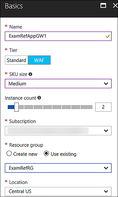
FIGURE 4-29 Completed Basics blade for App Gateway
The third step is the Settings blade where critical information is collected in regards to how the App Gateway will be deployed. The first selection is the Virtual Network where it will be deployed. A subnet will be selected next. Remember, the subnet will already have to be created before creating the App Gateway. In Figure 4-30, the App Gateway is being deployed to the ExamRefVNET into a subnet called AppGateway using a /26. Next will be the Frontend IP Configuration (this is important if this App Gateway will be made available to the internet or only the Intranet). Here you can select Public and then create a New Public IP Address. Additional selections will be the Protocol, Port, and WAF configurations.
)

FIGURE 4-30 Completed Settings blade for an internet facing App Gateway
Creating an App Gateway using the PowerShell
Creating an App Gateway using PowerShell is somewhat complex because there are many configurations that are required for this Virtual Appliance. These commands assume that your resource group was already created along with the VNet ExamRefVNET-PS that was created in earlier examples. You can walk through each part of the code to get an idea of how this created.
First you will create a new subnet in the VNet for the App Gateway instances. Remember, this subnet is only to be used by the App Gateway. This code will use the Get-AzureRMVirtualNetwork, Add-AzureRmVirtualNetworksubnetConfig and Set-AzureRmVirtualNetwork cmdlets.
# Create a subnet in the ExamRefVNET-PS VNet with the Address Range of 10.0.98.0/26
$vnet = Get-AzureRmVirtualNetwork -ResourceGroupName ExamRefRGPS `
                                  -Name ExamRefVNET-PS
Add-AzureRmVirtualNetworkSubnetConfig -Name AppGateway `
                                      -AddressPrefix "10.0.98.0/26" `
                                      -VirtualNetwork $vnet
Set-AzureRmVirtualNetwork -VirtualNetwork $vnet
The next step is to create the Public IP Address that will be used by the App Gateway. This code uses the New-AzureRMPublicIpAddress cmdlet. It is important to note that you can’t use a Static IP Address with the App Gateway.
# Create a Public IP address that is used to connect to the application gateway.
$publicip = New-AzureRmPublicIpAddress -ResourceGroupName ExamRefRGPS `
                                       -Name ExamRefAppGW-PubIP `
                                       -Location "Central US" `
                                       -AllocationMethod Dynamic
The following commands then used to create the various configurations for the App Gateway. Each of these commands use different cmdlets to load these configurations into variables that are ultimately passed to the New-AzureRmApplicationGateway cmdlet. Upon completion of the App Gateway, the last command will set the WAF configuration.
# Create a gateway IP configuration. The gateway picks up an IP address from the
 configured subnet
$vnet = Get-AzureRmvirtualNetwork -Name "ExamRefVNET-PS" -ResourceGroupName
 "ExamRefRGPS"
$subnet = Get-AzureRmVirtualNetworkSubnetConfig -Name "AppGateway" -VirtualNetwork
 $vnet
$gipconfig = New-AzureRmApplicationGatewayIPConfiguration -Name "AppGwSubnet01"
 -Subnet $subnet

# Configure a backend pool with the addresses of your web servers. You could add
 pool members here as well.
$pool = New-AzureRmApplicationGatewayBackendAddressPool -Name "appGatewayBackendPool"

# Configure backend http settings to determine the protocol and port that is used
 when sending traffic to the backend servers.
$poolSetting = New-AzureRmApplicationGatewayBackendHttpSettings -Name
                 "appGatewayBackendHttpSettings" `
                 -Port 80 `
Protocol Http `
 -CookieBasedAffinity Disabled `
 -RequestTimeout 30

# Configure a frontend port that is used to connect to the application gateway
 through the Public IP address
$fp = New-AzureRmApplicationGatewayFrontendPort -Name frontendport01 `
                                               -Port 80
# Configure the frontend IP configuration with the Public IP address created earlier.
$fipconfig = New-AzureRmApplicationGatewayFrontendIPConfig -Name fipconfig01 `
 -PublicIPAddress $publicip

# Configure the listener.  The listener is a combination of the front-end IP configuration, protocol, and port
$listener = New-AzureRmApplicationGatewayHttpListener -Name listener01 `
                                                 -Protocol Http `
                                                 -FrontendIPConfiguration $fipconfig `
                                                 -FrontendPort $fp

# Configure a basic rule that is used to route traffic to the backend servers.
$rule = New-AzureRmApplicationGatewayRequestRoutingRule -Name rule1 `
                                                        -RuleType Basic `
                                                        -BackendHttpSettings $poolSetting `
                                                        -HttpListener $listener `
                                                        -BackendAddressPool $pool

# Configure the SKU for the application gateway, this determines the size and
 whether WAF is used.
$sku = New-AzureRmApplicationGatewaySku -Name "WAF_Medium" `
                                        -Tier "WAF" `
                                        -Capacity 2
# Create the application gateway
New-AzureRmApplicationGateway -Name ExamRefAppGWPS `
                              -ResourceGroupName ExamRefRGPS `
                              -Location "Central US" `
                              -BackendAddressPools $pool `
                              -BackendHttpSettingsCollection $poolSetting `
                              -FrontendIpConfigurations $fipconfig  `
                              -GatewayIpConfigurations $gipconfig `
                              -FrontendPorts $fp `
                              -HttpListeners $listener `
                              -RequestRoutingRules $rule `
                              -Sku $sku `
                              -WebApplicationFirewallConfiguration

# Set WAF Configuration to Enabled
$AppGw = Get-AzureRmApplicationGateway -Name ExamRefAppGWPS -ResourceGroupName
 ExamRefRGPS
Set-AzureRmApplicationGatewayWebApplicationFirewallConfiguration -ApplicationGateway
 $AppGw `
                                                    -Enabled $True `
                                                    -FirewallMode "Detection" `
                                                    -RuleSetType "OWASP" `
                                                    -RuleSetVersion "3.0"
Creating the App Gateway using the Azure CLI
You will use the az network command with different arguments. The first step will be to create the AppGateway subnet. Next is the Public IP Address followed by the App Gateway Virtual Appliance. The command to create the App Gateway is quite large, but this is common when using the CLI. After the App Gateway has been provisioned, you will then enable the WAF using the az network application gateway command.
# Create a subnet for the App Gateway in the ExamRefVNET-CLI VNet with the Address
 Range of 10.0.98.0/26
az network vnet subnet create -g ExamRefRGCLI --vnet-name ExamRefVNET-CLI
                  -n AppGateway --address-prefix 10.0.98.0/26

# Create a Public IP address that is used to connect to the application gateway.
az network public-ip create -g ExamRefRGCLI -n ExamRefAppGW-PubIP

# Create the App gateway named ExamRefAppGWCLI
az network application-gateway create -n "ExamRefAppGWCLI" -g "ExamRefRGCLI"
--vnet-name "ExamRefVNET-CLI" --subnet "AppGateway" --capacity 2 --sku WAF_Medium
 --http-settings-cookie-based-affinity Disabled --http-settings-protocol Http
--frontend-port 80 --routing-rule-type Basic --http-settings-port 80
--public-ip-address "ExamRefAppGW-PubIP"

# Enable the WAF
az network application-gateway waf-config set -g "ExamRefRGCLI" -n "ExamRefAppGWCLI"
 --enabled true --rule-set-type OWASP --rule-set-version 3.0