Troubleshooting Windows Startup and Shutdown Problems
- By Mark E. Russinovich, Kate Chase, Alex Ionescu
- 9/15/2012
- Boot Process
- Troubleshooting Boot and Startup Problems
- Shutdown
- Conclusion
Understanding the details of the boot process will help you diagnose problems that can arise during a boot. Then we’ll explain the kinds of things that can go wrong during the boot process and how to resolve them. Finally, we’ll explain what occurs on an orderly system shutdown.
Boot Process
In describing the Windows boot process, we’ll start with the installation of Windows and proceed through the execution of boot support files. Device drivers are a crucial part of the boot process, so we’ll explain the way that they control the point in the boot process at which they load and initialize. Then we’ll describe how the executive subsystems initialize and how the kernel launches the user-mode portion of Windows by starting the Session Manager process (Smss.exe), which starts the initial two sessions (session 0 and session 1). Along the way, we’ll highlight the points at which various on-screen messages appear to help you correlate the internal process with what you see when you watch Windows boot.
The early phases of the boot process differ significantly on systems with a BIOS (basic input output system) versus systems with an EFI (Extensible Firmware Interface). EFI is a newer standard that does away with much of the legacy 16-bit code that BIOS systems use and allows the loading of preboot programs and drivers to support the operating system loading phase. The next sections describe the portions of the boot process specific to BIOS-based systems and are followed with a section describing the EFI-specific portions of the boot process.
To support these different firmware implementations (as well as EFI 2.0, which is known as Unified EFI, or UEFI), Windows provides a boot architecture that abstracts many of the differences away from users and developers in order to provide a consistent environment and experience regardless of the type of firmware used on the installed system.
BIOS Preboot
The Windows boot process doesn’t begin when you power on your computer or press the reset button. It begins when you install Windows on your computer. At some point during the execution of the Windows Setup program, the system’s primary hard disk is prepared with code that takes part in the boot process. Before we get into what this code does, let’s look at how and where Windows places the code on a disk. Since the early days of MS-DOS, a standard has existed on x86 systems for the way physical hard disks are divided into volumes.
Microsoft operating systems split hard disks into discrete areas known as partitions and use file systems (such as FAT and NTFS) to format each partition into a volume. A hard disk can contain up to four primary partitions. Because this apportioning scheme would limit a disk to four volumes, a special partition type, called an extended partition, further allocates up to four additional partitions within each extended partition. Extended partitions can contain extended partitions, which can contain extended partitions, and so on, making the number of volumes an operating system can place on a disk effectively infinite. Figure 13-1 shows an example of a hard disk layout, and Table 13-1 summarizes the files involved in the BIOS boot process. (You can learn more about Windows partitioning in Chapter 9.)
Table 13-1 Bios Boot Process Components
Component |
Processor Execution |
Responsibilities |
Location |
Master Boot Record (MBR) |
16-bit real mode |
Reads and loads the volume boot record (VBR) |
Per storage device |
Boot sector (also called volume boot record) |
16-bit real mode |
Understands the file system on the partition and locates Bootmgr by name, loading it into memory |
Per active (bootable) partition |
Bootmgr |
16-bit real mode and 32-bit without paging |
Reads the Boot Configuration Database (BCD), presents boot menu, and allows execution of preboot programs such as the Memory Test application (Memtest.exe). If a 64-bit installation is booted, switches to 64-bit long mode before loading Winload. |
Per system |
Winload.exe |
32-bit protected mode with paging, 64-bit protected mode if booting a Win64 installation |
Loads Ntoskrnl.exe and its dependencies (Bootvid.dll on 32-bit systems, Hal.dll, Kdcom.dll, Ci.dll, Clfs.sys, Pshed.dll) and boot-start device drivers. |
Per Windows installation |
Winresume.exe |
32-bit protected mode, 64-bit protected mode if resuming a Win64 installation |
If resuming after a hibernation state, resumes from the hibernation file (Hiberfil.sys) instead of typical Windows loading. |
Per Windows installation |
Memtest.exe |
32-bit protected mode |
If selected from the Boot Manager, starts up and provides a graphical interface for scanning memory and detecting damaged RAM. |
Per system |
Ntoskrnl.exe |
Protected mode with paging |
Initializes executive subsystems and boot and system-start device drivers, prepares the system for running native applications, and runs Smss.exe. |
Per Windows installation |
Hal.dll |
Protected mode with paging |
Kernel-mode DLL that interfaces Ntoskrnl and drivers to the hardware. It also acts as a driver for the motherboard itself, supporting soldered components that are not otherwise managed by another driver. |
Per Windows installation |
Smss.exe |
Native application |
Initial instance starts a copy of itself to initialize each session. The session 0 instance loads the Windows subsystem driver (Win32k.sys) and starts the Windows subsystem process (Csrss.exe) and Windows initialization process (Wininit.exe). All other per-session instances start a Csrss and Winlogon process. |
Per Windows installation |
Wininit.exe |
Windows application |
Starts the service control manager (SCM), the Local Security Authority process (LSASS), and the local session manager (LSM). Initializes the rest of the registry and performs user-mode initialization tasks. |
Per Windows installation |
Winlogon.exe |
Windows application |
Coordinates logon and user security, launches LogonUI. |
Per Windows installation |
Logonui.exe |
Windows application |
Presents interactive logon dialog box. |
Per Windows installation |
Services.exe |
Windows application |
Loads and initializes auto-start device drivers and Windows services. |
Per Windows installation |
)
Figure 13-1 Sample hard disk layout
Physical disks are addressed in units known as sectors. A hard disk sector on a BIOS PC is typically 512 bytes (but moving to 4,096 bytes; see Chapter 9 for more information). Utilities that prepare hard disks for the definition of volumes, such as the Windows Setup program, write a sector of data called a Master Boot Record (MBR) to the first sector on a hard disk. (MBR partitioning is described in Chapter 9.) The MBR includes a fixed amount of space that contains executable instructions (called boot code) and a table (called a partition table) with four entries that define the locations of the primary partitions on the disk. When a BIOS-based computer boots, the first code it executes is called the BIOS, which is encoded into the computer’s flash memory. The BIOS selects a boot device, reads that device’s MBR into memory, and transfers control to the code in the MBR.
The MBRs written by Microsoft partitioning tools, such as the one integrated into Windows Setup and the Disk Management MMC snap-in, go through a similar process of reading and transferring control. First, an MBR’s code scans the primary partition table until it locates a partition containing a flag (Active) that signals the partition is bootable. When the MBR finds at least one such flag, it reads the first sector from the flagged partition into memory and transfers control to code within the partition. This type of partition is called a system partition, and the first sector of such a partition is called a boot sectoror volume boot record(VBR). The volume defined for this partition is called the system volume.
Operating systems generally write boot sectors to disk without a user’s involvement. For example, when Windows Setup writes the MBR to a hard disk, it also writes the file system boot code (part of the boot sector) to a 100-MB bootable partition of the disk, marked as hidden to prevent accidental modification after the operating system has loaded. This is the system volume described earlier.
Before writing to a partition’s boot sector, Windows Setup ensures that the boot partition (the boot partition is the partition on which Windows is installed, which is typically not the same as the system partition, where the boot files are located) is formatted with NTFS, the only supported file system that Windows can boot from when installed on a fixed disk, or formats the boot partition (and any other partition) with NTFS. Note that the format of the system partition can be any format that Windows supports (such as FAT32). If partitions are already formatted appropriately, you can instruct Setup to skip this step. After Setup formats the system partition, Setup copies the Boot Manager program (Bootmgr) that Windows uses to the system partition (the system volume).
Another of Setup’s roles is to prepare the Boot Configuration Database (BCD), which on BIOS systems is stored in the \Boot\BCD file on the root directory of the system volume. This file contains options for starting the version of Windows that Setup installs and any preexisting Windows installations. If the BCD already exists, the Setup program simply adds new entries relevant to the new installation. For more information on the BCD, see Chapter 3, “System Mechanisms,” in Part 1.
The BIOS Boot Sector and Bootmgr
Setup must know the partition format before it writes a boot sector because the contents of the boot sector vary depending on the format. For a partition that is in NTFS format, Windows writes NTFS-capable code. The role of the boot-sector code is to give Windows information about the structure and format of a volume and to read in the Bootmgr file from the root directory of the volume. Thus, the boot-sector code contains just enough read-only file system code to accomplish this task. After the boot-sector code loads Bootmgr into memory, it transfers control to Bootmgr’s entry point. If the boot-sector code can’t find Bootmgr in the volume’s root directory, it displays the error message “BOOTMGR is missing”.
Bootmgr is actually a concatenation of a .com file (Startup.com) and an .exe file (Bootmgr.exe), so it begins its existence while a system is executing in an x86 operating mode called real mode, associated with .com files. In real mode, no virtual-to-physical translation of memory addresses occurs, which means that programs that use the memory addresses interpret them as physical addresses and that only the first 1 MB of the computer’s physical memory is accessible. Simple MS-DOS programs execute in a real-mode environment. However, the first action Bootmgr takes is to switch the system to protected mode. Still no virtual-to-physical translation occurs at this point in the boot process, but a full 32 bits of memory becomes accessible. After the system is in protected mode, Bootmgr can access all of physical memory. After creating enough page tables to make memory below 16 MB accessible with paging turned on, Bootmgr enables paging. Protected mode with paging enabled is the mode in which Windows executes in normal operation.
After Bootmgr enables protected mode, it is fully operational. However, it still relies on functions supplied by BIOS to access IDE-based system and boot disks as well as the display. Bootmgr’s BIOS-interfacing functions briefly switch the processor back to real mode so that services provided by the BIOS can be executed. Bootmgr next reads the BCD file from the \Boot directory using built-in file system code. Like the boot sector’s code, Bootmgr contains a lightweight NTFS file system library (Bootmgr also supports other file systems, such as FAT, El Torito CDFS, and UDFS, as well as WIM and VHD files); unlike the boot sector’s code, Bootmgr’s file system code can also read subdirectories.
Bootmgr next clears the screen. If Windows enabled the BCD setting to inform Bootmgr of a hibernation resume, this shortcuts the boot process by launching Winresume.exe, which will read the contents of the hibernation file into memory and transfer control to code in the kernel that resumes a hibernated system. That code is responsible for restarting drivers that were active when the system was shut down. Hiberfil.sys is only valid if the last computer shutdown was hibernation, since the hibernation file is invalidated after a resume, to avoid multiple resumes from the same point. (See the section The Power Manager in Chapter 8, for information on hibernation.)
If there is more than one boot-selection entry in the BCD, Bootmgr presents the user with the boot-selection menu (if there is only one entry, Bootmgr bypasses the menu and proceeds to launch Winload.exe). Selection entries in the BCD direct Bootmgr to the partition on which the Windows system directory (typically \Windows) of the selected installation resides. If Windows was upgraded from an older version, this partition might be the same as the system partition, or, on a clean install, it will always be the 100-MB hidden partition described earlier.
Entries in the BCD can include optional arguments that Bootmgr, Winload, and other components involved in the boot process interpret. Table 13-2 contains a list of these options and their effects for Bootmgr, Table 13-3 shows a list of BCD options for boot applications, and Table 13-4 shows BCD options for the Windows boot loader.
The Bcdedit.exe tool provides a convenient interface for setting a number of the switches. Some options that are included in the BCD are stored as command-line switches (“/DEBUG”, for example) to the registry value HKLM\SYSTEM\CurrentControlSet\Control\SystemStartOptions; otherwise, they are stored only in the BCD binary format in the BCD hive.
Table 13-2 BCD Options for the Windows Boot Manager (Bootmgr)
BCD Element |
Values |
Meaning |
bcdfilepath |
Path |
Points to the Boot Configuration Database (usually \Boot\BCD) file on the disk. |
displaybootmenu |
Boolean |
Determines whether the Boot Manager shows the boot menu or picks the default entry automatically. |
keyringaddress |
Physical address |
Specifies the physical address where the BitLocker key ring is located. |
noerrordisplay |
Boolean |
Silences the output of errors encountered by the Boot Manager. |
Resume |
Boolean |
Specifies whether or not resuming from hibernation should be attempted. This option is automatically set when Windows hibernates. |
Timeout |
Seconds |
Number of seconds that the Boot Manager should wait before choosing the default entry. |
resumeobject |
GUID |
Identifier for which boot application should be used to resume the system after hibernation. |
displayorder |
List |
Definition of the Boot Manager’s display order list. |
toolsdisplayorder |
List |
Definition of the Boot Manager’s tool display order list. |
bootsequence |
List |
Definition of the one-time boot sequence. |
Default |
GUID |
The default boot entry to launch. |
customactions |
List |
Definition of custom actions to take when a specific keyboard sequence has been entered. |
bcddevice |
GUID |
Device ID of where the BCD store is located. |
Table 13-3 BCD Options for Boot Applications
BCD Element |
Values |
Meaning |
avoidlowmemory |
Integer |
Forces physical addresses below the specified value to be avoided by the boot loader as much as possible. Sometimes required on legacy devices (such as ISA) where only memory below 16 MB is usable or visible. |
badmemoryaccess |
Boolean |
Forces usage of memory pages in the Bad Page List (see Chapter 10, for more information on the page lists). |
badmemorylist |
Array of page frame numbers (PFNs) |
Specifies a list of physical pages on the system that are known to be bad because of faulty RAM. |
baudrate |
Baud rate in bps |
Specifies an override for the default baud rate (19200) at which a remote kernel debugger host will connect through a serial port. |
bootdebug |
Boolean |
Enables remote boot debugging for the boot loader. With this option enabled, you can use Kd.exe or Windbg.exe to connect to the boot loader. |
bootems |
Boolean |
Used to cause Windows to enable Emergency Management Services (EMS) for boot applications, which reports boot information and accepts system management commands through a serial port. |
busparams |
String |
If a physical PCI debugging device is used to provide FireWire or serial debugging, specifies the PCI bus, function, and device number for the device. |
channel |
Channel between 0 and 62 |
Used in conjunction with {debugtype, 1394} to specify the IEEE 1394 channel through which kernel debugging communications will flow. |
configaccesspolicy |
Default, DisallowMmConfig |
Configures whether the system uses memory mapped I/O to access the PCI manufacturer’s configuration space or falls back to using the HAL’s I/O port access routines. Can sometimes be helpful in solving platform device problems. |
debugaddress |
Hardware address |
Specifies the hardware address of the serial (COM) port used for debugging. |
debugport |
COM port number |
Specifies an override for the default serial port (usually COM2 on systems with at least two serial ports) to which a remote kernel debugger host is connected. |
debugstart |
Active, AutoEnable, Disable |
Specifies settings for the debugger when kernel debugging is enabled. AutoEnable enables the debugger when a breakpoint or kernel exception, including kernel crashes, occurs. |
debugtype |
Serial, 1394, USB |
Specifies whether kernel debugging will be communicated through a serial, FireWire (IEEE 1394), or USB 2.0 port. (The default is serial.) |
emsbaudrate |
Baud rate in bps |
Specifies the baud rate to use for EMS. |
emsport |
COM port number |
Specifies the serial (COM) port to use for EMS. |
extendedinput |
Boolean |
Enables boot applications to leverage BIOS support for extended console input. |
firstmegabytepolicy |
UseNone, UseAll, UsePrivate |
Specifies how the low 1 MB of physical memory is consumed by the HAL to mitigate corruptions by the BIOS during power transitions. |
fontpath |
String |
Specifies the path of the OEM font that should be used by the boot application. |
graphicsmodedisabled |
Boolean |
Disables graphics mode for boot applications. |
graphicsresolution |
Resolution |
Sets the graphics resolution for boot applications. |
initialconsoleinput |
Boolean |
Specifies an initial character that the system inserts into the PC/AT keyboard input buffer. |
integrityservices |
Default, Disable, Enable |
Enables or disables code integrity services, which are used by Kernel Mode Code Signing. Default is Enabled. |
locale |
Localization string |
Sets the locale for the boot application (such as EN-US). |
noumex |
Boolean |
Disables user-mode exceptions when kernel debugging is enabled. If you experience system hangs (freezes) when booting in debugging mode, try enabling this option. |
novesa |
Boolean |
Disables the usage of VESA display modes. |
recoveryenabled |
Boolean |
Enables the recovery sequence, if any. Used by fresh installations of Windows to present the Windows PE-based Startup And Recovery interface. |
recoverysequence |
List |
Defines the recovery sequence (described above). |
relocatephysical |
Physical address |
Relocates an automatically selected NUMA node’s physical memory to the specified physical address. |
targetname |
String |
Defines the target name for the USB debugger when used with USB2 debugging {debugtype, usb}. |
testsigning |
Boolean |
Enables test-signing mode, which allows driver developers to load locally signed 64-bit drivers. This option results in a watermarked desktop. |
traditionalksegmappings |
Boolean |
Determines whether the kernel will honor the traditional KSEG0 mapping that was originally required for MIPS support. With KSEG0 mappings, the bottom 24 bits of the kernel’s initial virtual address space will map to the same physical address (that is, 0x80800000 virtual is 0x800000 in RAM). Disabling this requirement allows more low memory to be available, which can help with some hardware. |
truncatememory |
Address in bytes |
Disregards physical memory above the specified physical address. |
Table 13-4 BCD Options for the Windows Boot Loader (Winload)
BCD Element |
Values |
Meaning |
advancedoptions |
Boolean |
If false, executes the default behavior of launching the auto-recovery command boot entry when the boot fails; otherwise, displays the boot error and offers the user the advanced boot option menu associated with the boot entry. This is equivalent to pressing F8. |
bootlog |
Boolean |
Causes Windows to write a log of the boot to the file %SystemRoot%\Ntbtlog.txt. |
bootstatuspolicy |
DisplayAllFailures, IgnoreAllFailures, IgnoreShutdownFailures, IgnoreBootFailures |
Overrides the system’s default behavior of offering the user a troubleshooting boot menu if the system did not complete the previous boot or shutdown. |
bootux |
Disabled, Basic, Standard |
Defines the boot graphics user experience that the user will see. Disabled means that no graphics will be seen during boot time (only a black screen), while Basic will display only a progress bar during load. Standard displays the usual Windows logo animation during boot. |
clustermodeaddressing |
Number of processors |
Defines the maximum number of processors to include in a single Advanced Programmable Interrupt Controller (APIC) cluster. |
configflags |
Flags |
Specifies processor-specific configuration flags. |
dbgtransport |
Transport image name |
Overrides using one of the default kernel debugging transports (Kdcom.dll, Kd1394, Kdusb.dll) and instead uses the given file, permitting specialized debugging transports to be used that are not typically supported by Windows. |
debug |
Boolean |
Enables kernel-mode debugging. |
detecthal |
Boolean |
Enables the dynamic detection of the HAL. |
driverloadfailurepolicy |
Fatal, UseErrorControl |
Describes the loader behavior to use when a boot driver has failed to load. Fatal will prevent booting, while UseErrorControl causes the system to honor a driver’s default error behavior, specified in its service key. |
ems |
Boolean |
Instructs the kernel to use EMS as well. (If only bootems is used, only the boot loader will use EMS.) |
evstore |
String |
Stores the location of a boot preloaded hive. |
exportascd |
Boolean |
If this option is set, the kernel will treat the ramdisk file specified as an ISO image and not a Windows Installation Media (WIM) or System Deployment Image (SDI) file. |
groupaware |
Boolean |
Forces the system to use groups other than zero when associating the group seed to new processes. Used only on 64-bit Windows. |
groupsize |
Integer |
Forces the maximum number of logical processors that can be part of a group (maximum of 64). Can be used to force groups to be created on a system that would normally not require them to exist. Must be a power of 2, and is used only on 64-bit Windows. |
hal |
HAL image name |
Overrides the default file name for the HAL image (hal.dll). This option can be useful when booting a combination of a checked HAL and checked kernel (requires specifying the kernel element as well). |
halbreakpoint |
Boolean |
Causes the HAL to stop at a breakpoint early in HAL initialization. The first thing the Windows kernel does when it initializes is to initialize the HAL, so this breakpoint is the earliest one possible (unless boot debugging is used). If the switch is used without the /DEBUG switch, the system will elicit a blue screen with a STOP code of 0x00000078 (PHASE0_ EXCEPTION). |
hypervisorbaudrate |
Baud rate in bps |
If using serial hypervisor debugging, specifies the baud rate to use. |
hypervisorchannel |
Channel number from 0 to 62 |
If using FireWire (IEEE 1394) hypervisor debugging, specifies the channel number to use. |
hypervisordebug |
Boolean |
Enables debugging the hypervisor. |
hypervisordebugport |
COM port number |
If using serial hypervisor debugging, specifies the COM port to use. |
hypervisordebugtype |
Serial, 1394 |
Specifies which hardware port to use for hypervisor debugging. |
hypervisordisableslat |
Boolean |
Forces the hypervisor to ignore the presence of the Second Layer Address Translation (SLAT) feature if supported by the processor. |
hypervisorlaunchtype |
Off, Auto |
Enables loading of the hypervisor on a Hyper-V system, or forces it to be disabled. |
hypervisorpath |
Hypervisor binary image name |
Specifies the path of the hypervisor binary. |
hypervisoruselargevtlb |
Boolean |
Enables the hypervisor to use a larger amount of virtual TLB entries. |
increaseuserva |
Size in MB |
Increases the size of the user process address space from 2 GB to the specified size, up to 3 GB (and therefore reduces the size of system space). Giving virtual-memory-intensive applications such as database servers a larger address space can improve their performance. (See the section “Address Space Layout” in Chapter 9 for more information.) |
kernel |
Kernel image name |
Overrides the default file name for the kernel image (Ntoskrnl.exe). This option can be useful when booting a combination of a checked HAL and checked kernel (requires specifying the hal element to be used as well). |
lastknowngood |
Boolean |
Boots the last known good configuration, instead of the current control set. |
loadoptions |
Extra command-line parameters |
This option is used to add other command-line parameters that are not defined by BCD elements. These parameters could be used to configure or define the operation of other components on the system that might not be able to use the BCD (such as legacy components). |
maxgroup |
Boolean |
Maximizes the number of processor groups that are created during processor topology configuration. See Chapter 3 in Part 1 for more information about group selection and its relationship to NUMA. |
maxproc |
Boolean |
Forces the maximum number of supported processors that Windows will report to drivers and applications to accommodate the arrival of additional CPUs via dynamic processor support. |
msi |
Default, ForceDisable |
Allows disabling support for message signaled interrupts. |
nocrashautoreboot |
Boolean |
Disables the automatic reboot after a system crash (blue screen). |
nointegritychecks |
Boolean |
Disables integrity checks performed by Windows when loading drivers. Automatically removed at the next reboot. |
nolowmem |
Boolean |
Requires that PAE be enabled and that the system have more than 4 GB of physical memory. If these conditions are met, the PAE-enabled version of the Windows kernel, Ntkrnlpa.exe, won’t use the first 4 GB of physical memory. Instead, it will load all applications and device drivers and allocate all memory pools from above that boundary. This switch is useful only to test device-driver compatibility with large memory systems. |
numproc |
Number of processors |
Specifies the number of CPUs that can be used on a multiprocessor system. Example: /NUMPROC=2 on a four-way system will prevent Windows from using two of the four processors. |
nx |
OptIn, OptOut, AlwaysOff, AlwaysOn |
This option is available only on 32-bit versions of Windows when running on processors that support no-execute memory and only when PAE (explained further in the pae entry) is also enabled. It enables no-execute protection. No-execute protection is always enabled on 64-bit versions of Windows on x64 processors. See Chapter 9 for a description of this behavior. |
onecpu |
Boolean |
Causes Windows to use only one CPU on a multiprocessor system. |
optionsedit |
Boolean |
Enables the options editor in the Boot Manager. With this option, Boot Manager allows the user to interactively set on-demand command-line options and switches for the current boot. This is equivalent to pressing F10. |
osdevice |
GUID |
Specifies the device on which the operating system is installed. |
pae |
Default, ForceEnable, ForceDisable |
Default allows the boot loader to determine whether the system supports PAE and loads the PAE kernel. ForceEnable forces this behavior, while ForceDisable forces the loader to load the non–PAE version of the Windows kernel, even if the system is detected as supporting x86 PAEs and has more than 4 GB of physical memory. |
pciexpress |
Default, ForceDisable |
Can be used to disable support for PCI Express buses and devices. |
perfmem |
Size in MB |
Size of the buffer to allocate for performance data logging. This option acts similarly to the removememory element, since it prevents Windows from seeing the size specified as available memory. |
quietboot |
Boolean |
Instructs Windows not to initialize the VGA video driver responsible for presenting bitmapped graphics during the boot process. The driver is used to display boot progress information, so disabling it will disable the ability of Windows to show this information. |
ramdiskimagelength |
Length in bytes |
Size of the ramdisk specified. |
ramdiskimageoffset |
Offset in bytes |
If the ramdisk contains other data (such as a header) before the virtual file system, instructs the boot loader where to start reading the ramdisk file from. |
ramdisksdipath |
Image file name |
Specifies the name of the SDI ramdisk to load. |
ramdisktftpblocksize |
Block size |
If loading a WIM ramdisk from a network Trivial FTP (TFTP) server, specifies the block size to use. |
ramdisktftpclientport |
Port number |
If loading a WIM ramdisk from a network TFTP server, specifies the port. |
ramdisktftpwindowsize |
Window size |
If loading a WIM ramdisk from a network TFTP server, specifies the window size to use. |
removememory |
Size in bytes |
Specifies an amount of memory Windows won’t use. |
restrictapiccluster |
Cluster number |
Defines the largest APIC cluster number to be used by the system. |
resumeobject |
Object GUID |
Describes which application to use for resuming from hibernation, typically Winresume.exe. |
safeboot |
Minimal, Network, DsRepair |
Specifies options for a safe-mode boot. Minimal corresponds to safe mode without networking, Network to safe mode with networking, and DsRepair to safe mode with Directory Services Restore mode. (Safe mode is described later in this chapter.) |
safebootalternateshell |
Boolean |
Tells Windows to use the program specified by the HKLM\SYSTEM\CurrentControlSet\Control\SafeBoot\AlternateShell value as the graphical shell rather than the default, which is Windows Explorer. This option is referred to as Safe Mode With Command Prompt in the alternate boot menu. |
sos |
Boolean |
Causes Windows to list the device drivers marked to load at boot time and then to display the system version number (including the build number), amount of physical memory, and number of processors. |
stampdisks |
Boolean |
Specifies that Winload will write an MBR disk signature to a RAW disk when booting Windows PE (Preinstallation Environment). This can be required in deployment environments in order to create a mapping from operating system–enumerated hard disks to BIOS-enumerated hard disks to know which disk should be the system disk. |
systemroot |
String |
Specifies the path, relative to osdevice, in which the operating system is installed. |
targetname |
Name |
For USB 2.0 debugging, assigns a name to the machine that is being debugged. |
tpmbootentropy |
Default, ForceDisable, ForceEnable |
Forces a specific TPM Boot Entropy policy to be selected by the boot loader and passed on to the kernel. TPM Boot Entropy, when used, seeds the kernel’s random number generator (RNG) with data obtained from the TPM (if present). |
usefirmwarepcisettings |
Boolean |
Stops Windows from dynamically assigning IO/IRQ resources to PCI devices and leaves the devices configured by the BIOS. See Microsoft Knowledge Base article 148501 for more information. |
uselegacyapicmode |
Boolean |
Forces usage of basic APIC functionality even though the chipset reports extended APIC functionality as present. Used in cases of hardware errata and/or incompatibility. |
usephysicaldestination |
Boolean |
Forces the use of the APIC in physical destination mode. |
useplatformclock |
Boolean |
Forces usage of the platforms’s clock source as the system’s performance counter. |
vga |
Boolean |
Forces Windows to use the VGA display driver instead of the third-party high-performance driver. |
winpe |
Boolean |
Used by Windows PE, this option causes the configuration manager to load the registry SYSTEM hive as a volatile hive such that changes made to it in memory are not saved back to the hive image. |
x2apicpolicy |
Disabled, Enabled, Default |
Specifies whether extended APIC functionality should be used if the chipset supports it. Disabled is equivalent to setting uselegacyapicmode, while Enabled forces ACPI functionality on even if errata are detected. Default uses the chipset’s reported capabilities (unless errata are present). |
xsavepolicy |
Integer |
Forces the given XSAVE policy to be loaded from the XSAVE Policy Resource Driver (Hwpolicy.sys). |
xsaveaddfeature0-7 |
Integer |
Used while testing support for XSAVE on modern Intel processors; allows for faking that certain processor features are present when, in fact, they are not. This helps increase the size of the CONTEXT structure and confirms that applications work correctly with extended features that might appear in the future. No actual extra functionality will be present, however. |
xsaveremovefeature |
Integer |
Forces the entered XSAVE feature not to be reported to the kernel, even though the processor supports it. |
xsaveprocessorsmask |
Integer |
Bitmask of which processors the XSAVE policy should apply to. |
xsavedisable |
Boolean |
Turns off support for the XSAVE functionality even though the processor supports it. |
If the user doesn’t select an entry from the selection menu within the timeout period the BCD specifies, Bootmgr chooses the default selection specified in the BCD (if there is only one entry, it immediately chooses this one). Once the boot selection has been made, Bootmgr loads the boot loader associated with that entry, which will be Winload.exe for Windows installations.
Winload.exe also contains code that queries the system’s ACPI BIOS to retrieve basic device and configuration information. This information includes the following:
The time and date information stored in the system’s CMOS (nonvolatile memory)
The number, size, and type of disk drives on the system
Legacy device information, such as buses (for example, ISA, PCI, EISA, Micro Channel Architecture [MCA]), mice, parallel ports, and video adapters are not queried and instead faked out
This information is gathered into internal data structures that will be stored under the HKLM\HARDWARE\DESCRIPTION registry key later in the boot. This is mostly a legacy key as CMOS settings and BIOS-detected disk drive configuration settings, as well as legacy buses, are no longer supported by Windows, and this information is mainly stored for compatibility reasons. Today, it is the Plug and Play manager database that stores the true information on hardware.
Next, Winload begins loading the files from the boot volume needed to start the kernel initialization. The boot volume is the volume that corresponds to the partition on which the system directory (usually \Windows) of the installation being booted is located. The steps Winload follows here include:
Loads the appropriate kernel and HAL images (Ntoskrnl.exe and Hal.dll by default) as well as any of their dependencies. If Winload fails to load either of these files, it prints the message “Windows could not start because the following file was missing or corrupt”, followed by the name of the file.
Reads in the VGA font file (by default, vgaoem.fon). If this file fails, the same error message as described in step 1 will be shown.
Reads in the NLS (National Language System) files used for internationalization. By default, these are l_intl.nls, c_1252.nls, and c_437.nls.
Reads in the SYSTEM registry hive, \Windows\System32\Config\System, so that it can determine which device drivers need to be loaded to accomplish the boot. (A hive is a file that contains a registry subtree. You’ll find more details about the registry in Chapter 4, “Management Mechanisms,” in Part 1.)
Scans the in-memory SYSTEM registry hive and locates all the boot device drivers. Boot device drivers are drivers necessary to boot the system. These drivers are indicated in the registry by a start value of SERVICE_BOOT_START (0). Every device driver has a registry subkey under HKLM\SYSTEM\CurrentControlSet\Services. For example, Services has a subkey named fvevol for the BitLocker driver, which you can see in Figure 13-2. (For a detailed description of the Services registry entries, see the section “Services” in Chapter 4 in Part 1.)
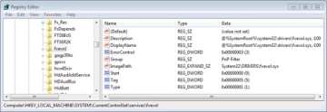
Figure 13-2 BitLocker driver service settings
Adds the file system driver that’s responsible for implementing the code for the type of partition (NTFS) on which the installation directory resides to the list of boot drivers to load. Winload must load this driver at this time; if it didn’t, the kernel would require the drivers to load themselves, a requirement that would introduce a circular dependency.
Loads the boot drivers, which should only be drivers that, like the file system driver for the boot volume, would introduce a circular dependency if the kernel was required to load them. To indicate the progress of the loading, Winload updates a progress bar displayed below the text “Starting Windows”. If the sos option is specified in the BCD, Winload doesn’t display the progress bar but instead displays the file names of each boot driver. Keep in mind that the drivers are loaded but not initialized at this time—they initialize later in the boot sequence.
Prepares CPU registers for the execution of Ntoskrnl.exe.
)
For steps 1 and 8, Winload also implements part of the Kernel Mode Code Signing (KMCS) infrastructure, which was described in Chapter 3 in Part 1, by enforcing that all boot drivers are signed on 64-bit Windows. Additionally, the system will crash if the signature of the early boot files is incorrect.
This action is the end of Winload’s role in the boot process. At this point, Winload calls the main function in Ntoskrnl.exe (KiSystemStartup) to perform the rest of the system initialization.
The UEFI Boot Process
A UEFI-compliant system has firmware that runs boot loader code that’s been programmed into the system’s nonvolatile RAM (NVRAM) by Windows Setup. The boot code reads the BCD’s contents, which are also stored in NVRAM. The Bcdedit.exe tool mentioned earlier also has the ability to abstract the firmware’s NVRAM variables in the BCD, allowing for full transparency of this mechanism.
The UEFI standard defines the ability to prompt the user with an EFI Boot Manager that can be used to select an operating system or additional applications to load. However, to provide a consistent user interface between BIOS systems and UEFI systems, Windows sets a 2-second timeout for selecting the EFI Boot Manager, after which the EFI-version of Bootmgr (Bootmgfw.efi) loads instead.
Hardware detection occurs next, where the boot loader uses UEFI interfaces to determine the number and type of the following devices:
Network adapters
Video adapters
Keyboards
Disk controllers
Storage devices
On UEFI systems, all operations and programs execute in the native CPU mode with paging enabled and no part of the Windows boot process executes in 16-bit mode. Note that although EFI is supported on both 32-bit and 64-bit systems, Windows provides support for EFI only on 64-bit platforms.
Just as Bootmgr does on x86 and x64 systems, the EFI Boot Manager presents a menu of boot selections with an optional timeout. Once a boot selection is made, the loader navigates to the subdirectory on the EFI System partition corresponding to the selection and loads the EFI version of the Windows boot loader (Winload.efi).
The UEFI specification requires that the system have a partition designated as the EFI System partition that is formatted with the FAT file system and is between 100 MB and 1 GB in size or up to 1 percent of the size of the disk, and each Windows installation has a subdirectory on the EFI System partition under EFI\Microsoft.
Note that thanks to the unified boot process and model present in Windows, the components in Table 13-1 apply almost identically to UEFI systems, except that those ending in .exe end in .efi, and they use EFI APIs and services instead of BIOS interrupts. Another difference is that to avoid limitations of the MBR partition format (including a maximum of four partitions per disk), UEFI systems use the GPT (GUID Partition Table) format, which uses GUIDs to identify different partitions and their roles on the system.
Booting from iSCSI
Internet SCSI (iSCSI) devices are a kind of network-attached storage, in that remote physical disks are connected to an iSCSI Host Bus Adapter (HBA) or through Ethernet. These devices, however, are different from traditional network-attached storage (NAS) because they provide block-level access to disks, unlike the logical-based access over a network file system that NAS employs. Therefore, an iSCSI-connected disk appears as any other disk drive, both to the boot loader as well as to the OS, as long as the Microsoft iSCSI Initiator is used to provide access over an Ethernet connection. By using iSCSI-enabled disks instead of local storage, companies can save on space, power consumption, and cooling.
Although Windows has traditionally supported booting only from locally connected disks, or network booting through PXE, modern versions of Windows are also capable of natively booting from iSCSI devices through a mechanism called iSCSI Boot. The boot loader (Winload.exe) contains a minimalistic network stack conforming to the Universal Network Device Interface (UNDI) standard, which allows compatible NIC ROMs to respond to Interrupt 13h (the legacy BIOS disk I/O interrupt) and convert the requests to network I/O. On EFI systems, the network interface driver provided by the manufacturer is used instead, and EFI Device APIs are used instead of interrupts.
Finally, to know the location, path, and authentication information for the remote disk, the boot loader also reads an iSCSI Boot Firmware Table (iBFT) that must be present in physical memory (typically exposed through ACPI). Additionally, Windows Setup also has the capability of reading this table to determine bootable iSCSI devices and allow direct installation on such a device, such that no imaging is required. Combined with the Microsoft iSCSI Initiator, this is all that’s required for Windows to boot from iSCSI, as shown in Figure 13-3.
)
Figure 13-3 iSCSI boot architecture
Initializing the Kernel and Executive Subsystems
When Winload calls Ntoskrnl, it passes a data structure called the loader parameter block that contains the system and boot partition paths, a pointer to the memory tables Winload generated to describe the physical memory on the system, a physical hardware tree that is later used to build the volatile HARDWARE registry hive, an in-memory copy of the SYSTEM registry hive, and a pointer to the list of boot drivers Winload loaded, as well as various other information related to the boot processing performed until this point.
EXPERIMENT: Loader Parameter Block
While booting, the kernel keeps a pointer to the loader parameter block in the KeLoaderBlock variable. The kernel discards the parameter block after the first boot phase, so the only way to see the contents of the structure is to attach a kernel debugger before booting and break at the initial kernel debugger breakpoint. If you are able to do so, you can use the dt command to dump the block, as shown:
0: kd> dt poi(nt!KeLoaderBlock) nt!_LOADER_PARAMETER_BLOCK
   +0x000 OsMajorVersion      : 6
   +0x004 OsMinorVersion      : 1
   +0x008 Size                : 0x88
   +0x00c Reserved            : 0
   +0x010 LoadOrderListHead   : _LIST_ENTRY [ 0x8085b4c8 - 0x80869c70 ]
   +0x018 MemoryDescriptorListHead :
                    _LIST_ENTRY [ 0x80a00000 - 0x80a00de8 ]
   +0x020 BootDriverListHead  : _LIST_ENTRY [ 0x80860d10 - 0x8085eba0 ]
   +0x028 KernelStack         : 0x88e7c000
   +0x02c Prcb                : 0
   +0x030 Process             : 0
   +0x034 Thread              : 0x88e64800
   +0x038 RegistryLength      : 0x2940000
   +0x03c RegistryBase        : 0x80adf000 Void
   +0x040 ConfigurationRoot   : 0x8082d450 _CONFIGURATION_COMPONENT_DATA
   +0x044 ArcBootDeviceName   : 0x8082d9a0
                    "multi(0)disk(0)rdisk(0)partition(4)"
   +0x048 ArcHalDeviceName    : 0x8082d788
                    "multi(0)disk(0)rdisk(0)partition(4)"
   +0x04c NtBootPathName      : 0x8082d828  "\Windows\"
   +0x050 NtHalPathName       : 0x80826358  "\"
   +0x054 LoadOptions         : 0x8080e1b0
                    "NOEXECUTE=ALWAYSON DEBUGPORT=COM1
                                    BAUDRATE=115200"
   +0x058 NlsData             : 0x808691e0 _NLS_DATA_BLOCK
   +0x05c ArcDiskInformation  : 0x80821408 _ARC_DISK_INFORMATION
   +0x060 OemFontFile         : 0x84a551d0 Void
   +0x064 Extension           : 0x8082d9d8 _LOADER_PARAMETER_EXTENSION
   +0x068 u                   : <unnamed-tag>
   +0x074 FirmwareInformation : _FIRMWARE_INFORMATION_LOADER_BLOCK
_LIST_ENTRY [ 0x80a00000 - 0x80a00de8 ]
+0x020 BootDriverListHead : _LIST_ENTRY [ 0x80860d10 - 0x8085eba0 ]
+0x028 KernelStack : 0x88e7c000
+0x02c Prcb : 0
+0x030 Process : 0
+0x034 Thread : 0x88e64800
+0x038 RegistryLength : 0x2940000
+0x03c RegistryBase : 0x80adf000 Void
+0x040 ConfigurationRoot : 0x8082d450 _CONFIGURATION_COMPONENT_DATA
+0x044 ArcBootDeviceName : 0x8082d9a0
"multi(0)disk(0)rdisk(0)partition(4)"
+0x048 ArcHalDeviceName : 0x8082d788
"multi(0)disk(0)rdisk(0)partition(4)"
+0x04c NtBootPathName : 0x8082d828 "\Windows\"
+0x050 NtHalPathName : 0x80826358 "\"
+0x054 LoadOptions : 0x8080e1b0
"NOEXECUTE=ALWAYSON DEBUGPORT=COM1
BAUDRATE=115200"
+0x058 NlsData : 0x808691e0 _NLS_DATA_BLOCK
+0x05c ArcDiskInformation : 0x80821408 _ARC_DISK_INFORMATION
+0x060 OemFontFile : 0x84a551d0 Void
+0x064 Extension : 0x8082d9d8 _LOADER_PARAMETER_EXTENSION
+0x068 u : <unnamed-tag>
+0x074 FirmwareInformation : _FIRMWARE_INFORMATION_LOADER_BLOCK
Additionally, the !loadermemorylist command can be used on the MemoryDescriptorListHead field to dump the physical memory ranges:
0: kd> !loadermemorylist 0x80a00000
Base Length      Type
1    00000001    HALCachedMemory
2    00000004    HALCachedMemory
...
4a32    00000023    NlsData
4a55    00000002    BootDriver
4a57    00000026    BootDriver
4a7d    00000014    BootDriver
4a91    0000016f    Free
4c00    0001b3f0    Free
1fff0    00000001    FirmwarePermanent
1fff1    00000002    FirmwarePermanent
1fff3    00000001    FirmwarePermanent
1fff4    0000000b    FirmwarePermanent
1ffff    00000001    FirmwarePermanent
fd000    00000800    FirmwarePermanent
fec00    00000001    FirmwarePermanent
fee00    00000001    FirmwarePermanent
ffc00    00000400    FirmwarePermanent

Summary
Memory Type         Pages
Free                0001bc50   (  113744)
LoadedProgram       0000013d   (     317)
FirmwareTemporary   000006dd   (    1757)
FirmwarePermanent   00000c37   (    3127)
OsloaderHeap        0000022a   (     554)
SystemCode          000005dc   (    1500)
BootDriver          00000968   (    2408)
RegistryData        00002940   (   10560)
MemoryData          00000035   (      53)
NlsData             00000023   (      35)
HALCachedMemory     0000001e   (      30)
                    ========    ========
Total               00020bc5   (  134085) = ~523MB
Ntoskrnl then begins phase 0, the first of its two-phase initialization process (phase 1 is the second). Most executive subsystems have an initialization function that takes a parameter that identifies which phase is executing.
During phase 0, interrupts are disabled. The purpose of this phase is to build the rudimentary structures required to allow the services needed in phase 1 to be invoked. Ntoskrnl’s main function calls KiSystemStartup, which in turn calls HalInitializeProcessor and KiInitializeKernel for each CPU. KiInitializeKernel, if running on the boot CPU, performs systemwide kernel initialization, such as initializing internal lists and other data structures that all CPUs share. It also checks whether virtualization was specified as a BCD option (hypervisorlaunchtype), and whether the CPU supports hardware virtualization technology. The first instance of KiInitializeKernel then calls the function responsible for orchestrating phase 0, InitBootProcessor, while subsequent processors only call HalInitSystem.
InitBootProcessor starts by initializing the pool look-aside pointers for the initial CPU and by checking for and honoring the BCD burnmemory boot option, where it discards the amount of physical memory the value specifies. It then performs enough initialization of the NLS files that were loaded by Winload (described earlier) to allow Unicode to ANSI and OEM translation to work. Next, it continues by calling the HAL function HalInitSystem, which gives the HAL a chance to gain system control before Windows performs significant further initialization. One responsibility of HalInitSystem is to prepare the system interrupt controller of each CPU for interrupts and to configure the interval clock timer interrupt, which is used for CPU time accounting. (See the section “Quantum Accounting” in Chapter 5, “Processes, Threads, and Jobs,” in Part 1 for more on CPU time accounting.)
When HalInitSystem returns control, InitBootProcessor proceeds by computing the reciprocal for timer expiration. Reciprocals are used for optimizing divisions on most modern processors. They can perform multiplications faster, and because Windows must divide the current 64-bit time value in order to find out which timers need to expire, this static calculation reduces interrupt latency when the clock interval fires. InitBootProcessor then continues by setting up the system root path and searching the kernel image for the location of the crash message strings it displays on blue screens, caching their location to avoid looking up the strings during a crash, which could be dangerous and unreliable. Next, InitBootProcessor initializes the quota functionality part of the process manager and reads the control vector. This data structure contains more than 150 kernel-tuning options that are part of the HKLM\SYSTEM\CurrentControlSet\Control registry key, including information such as the licensing data and version information for the installation.
InitBootProcessor is now ready to call the phase 0 initialization routines for the executive, Driver Verifier, and the memory manager. These components perform the following initialization steps:
The executive initializes various internal locks, resources, lists, and variables and validates that the product suite type in the registry is valid, discouraging casual modification of the registry in order to “upgrade” to an SKU of Windows that was not actually purchased. This is only one of the many such checks in the kernel.
Driver Verifier, if enabled, initializes various settings and behaviors based on the current state of the system (such as whether safe mode is enabled) and verification options. It also picks which drivers to target for tests that target randomly chosen drivers.
The memory manager constructs page tables and internal data structures that are necessary to provide basic memory services. It also builds and reserves an area for the system file cache and creates memory areas for the paged and nonpaged pools (described in Chapter 10). The other executive subsystems, the kernel, and device drivers use these two memory pools for allocating their data structures.
Next, InitBootProcessor calls HalInitializeBios to set up the BIOS emulation code part of the HAL. This code is used both on real BIOS systems as well as on EFI systems to allow access (or to emulate access) to 16-bit real mode interrupts and memory, which are used mainly by Bootvid to display the early VGA boot screen and bugcheck screen. After the function returns, the kernel initializes the Bootvid library and displays early boot status messages by calling InbvEnableBootDriver and InbvDriverInitailize.
At this point, InitBootProcessor enumerates the boot-start drivers that were loaded by Winload and calls DbgLoadImageSymbols to inform the kernel debugger (if attached) to load symbols for each of these drivers. If the host debugger has configured the break on symbol load option, this will be the earliest point for a kernel debugger to gain control of the system. InitBootProcessor now calls HvlInitSystem, which attempts to connect to the hypervisor in case Windows might be running inside a Hyper-V host system’s child partition. When the function returns, it calls HeadlessInit to initialize the serial console if the machine was configured for Emergency Management Services (EMS).
Next, InitBootProcessor builds the versioning information that will be used later in the boot process, such as the build number, service pack version, and beta version status. Then it copies the NLS tables that Winload previously loaded into paged pool, re-initializes them, and creates the kernel stack trace database if the global flags specify creating one. (For more information on the global flags, see Chapter 3 in Part 1.)
Finally, InitBootProcessor calls the object manager, security reference monitor, process manager, user-mode debugging framework, and the Plug and Play manager. These components perform the following initialization steps:
During the object manager initialization, the objects that are necessary to construct the object manager namespace are defined so that other subsystems can insert objects into it. A handle table is created so that resource tracking can begin.
The security reference monitor initializes the token type object and then uses the object to create and prepare the first local system account token for assignment to the initial process. (See Chapter 6, “Security,” in Part 1 for a description of the local system account.)
The process manager performs most of its initialization in phase 0, defining the process and thread object types and setting up lists to track active processes and threads. The process manager also creates a process object for the initial process and names it Idle. As its last step, the process manager creates the System process and a system thread to execute the routine Phase1Initialization. This thread doesn’t start running right away because interrupts are still disabled.
The user-mode debugging framework creates the definition of the debug object type that is used for attaching a debugger to a process and receiving debugger events. For more information on user-mode debugging, see Chapter 3 in Part 1.
The Plug and Play manager’s phase 0 initialization then takes place, which involves simply initializing an executive resource used to synchronize access to bus resources.
When control returns to KiInitializeKernel, the last step is to allocate the DPC stack for the current processor and the I/O privilege map save area (on x86 systems only), after which control proceeds to the Idle loop, which then causes the system thread created in step 3 of the previous process description to begin executing phase 1. (Secondary processors wait to begin their initialization until step 8 of phase 1, described in the following list.)
Phase 1 consists of the following steps:
Phase1InitializationDiscard, which, as the name implies, discards the code that is part of the INIT section of the kernel image in order to preserve memory.
The initialization thread sets its priority to 31, the highest possible, in order to prevent preemption.
The NUMA/group topology relationships are created, in which the system tries to come up with the most optimized mapping between logical processors and processor groups, taking into account NUMA localities and distances, unless overridden by the relevant BCD settings.
HalInitSystem prepares the system to accept interrupts from devices and to enable interrupts.
The boot video driver is called, which in turn displays the Windows startup screen, which by default consists of a black screen and a progress bar. If the quietboot boot option was used, this step will not occur.
The kernel builds various strings and version information, which are displayed on the boot screen through Bootvid if the sos boot option was enabled. This includes the full version information, number of processors supported, and amount of memory supported.
The power manager’s initialization is called.
The system time is initialized (by calling HalQueryRealTimeClock) and then stored as the time the system booted.
On a multiprocessor system, the remaining processors are initialized by KeStartAllProcessors and HalAllProcessorsStarted. The number of processors that will be initialized and supported depends on a combination of the actual physical count, the licensing information for the installed SKU of Windows, boot options such as numproc and onecpu, and whether dynamic partitioning is enabled (server systems only). After all the available processors have initialized, the affinity of the system process is updated to include all processors.
The object manager creates the namespace root directory (\), \ObjectTypes directory, and the DOS device name mapping directory (\Global??). It then creates the \DosDevices symbolic link that points at the Windows subsystem device name mapping directory.
The executive is called to create the executive object types, including semaphore, mutex, event, and timer.
The I/O manager is called to create the I/O manager object types, including device, driver, controller, adapter, and file objects.
The kernel debugger library finalizes initialization of debugging settings and parameters if the debugger has not been triggered prior to this point.
The transaction manager also creates its object types, such as the enlistment, resource manager, and transaction manager types.
The kernel initializes scheduler (dispatcher) data structures and the system service dispatch table.
The user-mode debugging library (Dbgk) data structures are initialized.
If Driver Verifier is enabled and, depending on verification options, pool verification is enabled, object handle tracing is started for the system process.
The security reference monitor creates the \Security directory in the object manager namespace and initializes auditing data structures if auditing is enabled.
The \SystemRoot symbolic link is created.
The memory manager is called to create the \Device\PhysicalMemory section object and the memory manager’s system worker threads (which are explained in Chapter 10).
NLS tables are mapped into system space so that they can be easily mapped by user-mode processes.
Ntdll.dll is mapped into the system address space.
The cache manager initializes the file system cache data structures and creates its worker threads.
The configuration manager creates the \Registry key object in the object manager namespace and opens the in-memory SYSTEM hive as a proper hive file. It then copies the initial hardware tree data passed by Winload into the volatile HARDWARE hive.
The high-resolution boot graphics library initializes, unless it has been disabled through the BCD or the system is booting headless.
The errata manager initializes and scans the registry for errata information, as well as the INF (driver installation file, described in Chapter 8) database containing errata for various drivers.
Superfetch and the prefetcher are initialized.
The Store Manager is initialized.
The current time zone information is initialized.
Global file system driver data structures are initialized.
Phase 1 of debugger-transport-specific information is performed by calling the KdDebuggerInitialize1 routine in the registered transport, such as Kdcom.dll.
The Plug and Play manager calls the Plug and Play BIOS.
The advanced local procedure call (ALPC) subsystem initializes the ALPC port type and ALPC waitable port type objects. The older LPC objects are set as aliases.
If the system was booted with boot logging (with the BCD bootlog option), the boot log file is initialized. If the system was booted in safe mode, a string is displayed on the boot screen with the current safe mode boot type.
The executive is called to execute its second initialization phase, where it configures part of the Windows licensing functionality in the kernel, such as validating the registry settings that hold license data. Also, if persistent data from boot applications is present (such as memory diagnostic results or resume from hibernation information), the relevant log files and information are written to disk or to the registry.
The MiniNT/WinPE registry keys are created if this is such a boot, and the NLS object directory is created in the namespace, which will be used later to host the section objects for the various memory-mapped NLS files.
The power manager is called to initialize again. This time it sets up support for power requests, the ALPC channel for brightness notifications, and profile callback support.
The I/O manager initialization now takes place. This stage is a complex phase of system startup that accounts for most of the boot time.
The I/O manager first initializes various internal structures and creates the driver and device object types. It then calls the Plug and Play manager, power manager, and HAL to begin the various stages of dynamic device enumeration and initialization. (Because this process is complex and specific to the I/O system, we cover the details in Chapter 8.) Then the Windows Management Instrumentation (WMI) subsystem is initialized, which provides WMI support for device drivers. (See the section “Windows Management Instrumentation” in Chapter 4 in Part 1 for more information.) This also initializes Event Tracing for Windows (ETW). Next, all the boot-start drivers are called to perform their driver-specific initialization, and then the system-start device drivers are loaded and initialized. (Details on the processing of the driver load control information on the registry are also covered in Chapter 8.) Finally, the Windows subsystem device names are created as symbolic links in the object manager’s namespace.
The transaction manager sets up the Windows software trace preprocessor (WPP) and ETW and initializes with WMI. (ETW and WMI are described in Chapter 4 in Part 1.)
Now that boot-start and system-start drivers are loaded, the errata manager loads the INF database with the driver errata and begins parsing it, which includes applying registry PCI configuration workarounds.
If the computer is booting in safe mode, this fact is recorded in the registry.
Unless explicitly disabled in the registry, paging of kernel-mode code (in Ntoskrnl and drivers) is enabled.
The configuration manager makes sure that all processors on an SMP system are identical in terms of the features that they support; otherwise, it crashes the system.
On 32-bit systems, VDM (Virtual Dos Machine) support is initialized, which includes determining whether the processor supports Virtual Machine Extensions (VME).
The process manager is called to set up rate limiting for jobs, initialize the static environment for protected processes, and look up the various system-defined entry points in the user-mode system library (Ntdll.dll).
The power manager is called to finalize its initialization.
The rest of the licensing information for the system is initialized, including caching the current policy settings stored in the registry.
The security reference monitor is called to create the Command Server Thread that communicates with LSASS. (See the section “Security System Components” in Chapter 6 in Part 1 for more on how security is enforced in Windows.)
The Session Manager (Smss) process (introduced in Chapter 2, “System Architecture,” in Part 1) is started. Smss is responsible for creating the user-mode environment that provides the visible interface to Windows—its initialization steps are covered in the next section.
The TPM boot entropy values are queried. These values can be queried only once per boot, and normally, the TPM system driver should have queried them by now, but if this driver had not been running for some reason (perhaps the user disabled it), the unqueried values would still be available. Therefore, the kernel manually queries them too to avoid this situation, and in normal scenarios, the kernel’s own query should fail.
All the memory used up by the loader parameter block and all its references is now freed.
As a final step before considering the executive and kernel initialization complete, the phase 1 initialization thread waits for the handle to the Session Manager process with a timeout value of 5 seconds. If the Session Manager process exits before the 5 seconds elapse, the system crashes with a SESSION5_INITIALIZATION_FAILED stop code.
If the 5-second wait times out (that is, if 5 seconds elapse), the Session Manager is assumed to have started successfully, and the phase 1 initialization function calls the memory manager’s zero page thread function (explained in Chapter 10). Thus, this system thread becomes the zero page thread for the remainder of the life of the system.
Smss, Csrss, and Wininit
Smss is like any other user-mode process except for two differences. First, Windows considers Smss a trusted part of the operating system. Second, Smss is a native application. Because it’s a trusted operating system component, Smss can perform actions few other processes can perform, such as creating security tokens. Because it’s a native application, Smss doesn’t use Windows APIs—it uses only core executive APIs known collectively as the Windows native API. Smss doesn’t use the Win32 APIs because the Windows subsystem isn’t executing when Smss launches. In fact, one of Smss’s first tasks is to start the Windows subsystem.
Smss then calls the configuration manager executive subsystem to finish initializing the registry, fleshing the registry out to include all its keys. The configuration manager is programmed to know where the core registry hives are stored on disk (excluding hives corresponding to user profiles), and it records the paths to the hives it loads in the HKLM\SYSTEM\CurrentControlSet\Control\hivelist key.
The main thread of Smss performs the following initialization steps:
Marks itself as a critical process and its main thread as a critical thread. As discussed in Chapter 5 in Part 1, this will cause the kernel to crash the system if Smss quits unexpectedly. Smss also enables the automatic affinity update mode to support dynamic processor addition. (See Chapter 5 in Part 1 for more information.)
Creates protected prefixes for the mailslot and named pipe file system drivers, creating privileged paths for administrators and service accounts to communicate through those paths. See Chapter 7, “Networking,” in Part 1 for more information.
Calls SmpInit, which tunes the maximum concurrency level for Smss, meaning the maximum number of parallel sessions that will be created by spawning copies of Smss into other sessions. This is at least four and at most the number of active CPUs.
SmpInit then creates an ALPC port object (\SmApiPort) to receive client requests (such as to load a new subsystem or create a session).
SmpInit calls SmpLoadDataFromRegistry, which starts by setting up the default environment variables for the system, and sets the SAFEBOOT variable if the system was booted in safe mode.
SmpLoadDataFromRegistry calls SmpInitializeDosDevices to define the symbolic links for MS-DOS device names (such as COM1 and LPT1).
SmpLoadDataFromRegistry creates the \Sessions directory in the object manager’s namespace (for multiple sessions).
SmpLoadDataFromRegistry runs any programs defined in HKLM\SYSTEM\CurrentControlSet\Control\Session Manager\BootExecute with SmpExecuteCommand. Typically, this value contains one command to run Autochk (the boot-time version of Chkdsk).
SmpLoadDataFromRegistry calls SmpProcessFileRenames to perform delayed file rename and delete operations as directed by HKLM\SYSTEM\CurrentControlSet\Control\Session Manager\PendingFileRenameOperations and HKLM\SYSTEM\CurrentControlSet\Control\Session Manager\PendingFileRenameOperations2.
SmpLoadDataFromRegistry calls SmpCreatePagingFiles to create additional paging files. Paging file configuration is stored under HKLM\SYSTEM\CurrentControlSet\Control\Session Manager\Memory Management\PagingFiles.
SmpLoadDataFromRegistry initializes the registry by calling the native function NtInitializeRegistry. The configuration manager builds the rest of the registry by loading the registry hives for the HKLM\SAM, HKLM\SECURITY, and HKLM\SOFTWARE keys. Although HKLM\SYSTEM\CurrentControlSet\Control\hivelist locates the hive files on disk, the configuration manager is coded to look for them in \Windows\System32\Config.
SmpLoadDataFromRegistry calls SmpCreateDynamicEnvironmentVariables to add system environment variables that are defined in HKLM\SYSTEM\CurrentControlSet\Session Manager\Environment, as well as processor-specific environment variables such as NUMBER_PROCESSORS, PROCESSOR_ARCHITECTURE, and PROCESSOR_LEVEL.
SmpLoadDataFromRegistry runs any programs defined in HKLM\SYSTEM\CurrentControlSet\Control\Session Manager\SetupExecute with SmpExecuteCommand. Typically, this value is set only if Windows is being booted as part of the second stage of installation and Setupcl.exe is the default value.
SmpLoadDataFromRegistry calls SmpConfigureSharedSessionData to initialize the list of subsystems that will be started in each session (both immediately and deferred) as well as the Session 0 initialization command (which, by default, is to launch the Wininit.exe process). The initialization command can be overridden by creating a string value called S0InitialCommand in HKLM\SYSTEM\CurrentControlSet\Control\Session Manager and setting it as the path to another program.
SmpLoadDataFromRegistry calls SmpInitializeKnownDlls to open known DLLs, and creates section objects for them in the \Knowndlls directory of the object manager namespace. The list of DLLs considered known is located in HKLM\SYSTEM\CurrentControlSet\Control\Session Manager\KnownDLLs, and the path to the directory in which the DLLs are located is stored in the DllDirectory value of the key. On 64-bit systems, 32-bit DLLs used as part of Wow64 are stored in the DllDirectory32 value.
Finally, SmpLoadDataFromRegistry calls SmpTranslateSystemPartitionInformation to convert the SystemPartition value stored in HKLM\SYSTEM\Setup, which is stored in native NT object manager path format, to a volume drive letter stored in the BootDir value. Among other components, Windows Update uses this registry key to figure out what the system volume is.
At this point, SmpLoadDataFromRegistry returns to SmpInit, which returns to the main thread entry point. Smss then creates the number of initial sessions that were defined (typically, only one, session 0, but you can change this number through the NumberOfInitialSessions registry value in the Smss registry key mentioned earlier) by calling SmpCreateInitialSession, which creates an Smss process for each user session. This function’s main job is to call SmpStartCsr to start Csrss in each session.
As part of Csrss’s initialization, it loads the kernel-mode part of the Windows subsystem (Win32k.sys). The initialization code in Win32k.sys uses the video driver to switch the screen to the resolution defined by the default profile, so this is the point at which the screen changes from the VGA mode the boot video driver uses to the default resolution chosen for the system.
Meanwhile, each spawned Smss in a different user session starts the other subsystem processes, such as Psxss if the Subsystem for Unix-based Applications feature was installed. (See Chapter 3 in Part 1 for more information on subsystem processes.)
The first Smss from session 0 executes the Session 0 initialization command (described in step 14), by default launching the Windows initialization process (Wininit). Other Smss instances start the interactive logon manager process (Winlogon), which, unlike Wininit, is hardcoded. The startup steps of Wininit and Winlogon are described shortly.
After performing these initialization steps, the main thread in Smss waits forever on the process handle of Winlogon, while the other ALPC threads wait for messages to create new sessions or subsystems. If either Wininit or Csrss terminate unexpectedly, the kernel crashes the system because these processes are marked as critical. If Winlogon terminates unexpectedly, the session associated with it is logged off.
Wininit then performs its startup steps, such as creating the initial window station and desktop objects. It also configures the Session 0 window hook, which is used by the Interactive Services Detection service (UI0Detect.exe) to provide backward compatibility with interactive services. (See Chapter 4 in Part 1 for more information on services.) Wininit then creates the service control manager (SCM) process (%SystemRoot%\System32\Services.exe), which loads all services and device drivers marked for auto-start, and the Local Security Authority subsystem (LSASS) process (%SystemRoot%\System32\Lsass.exe). Finally, it loads the local session manager (%SystemRoot%\System32\Lsm.exe). On session 1 and beyond, Winlogon runs instead and loads the registered credential providers for the system (by default, the Microsoft credential provider supports password-based and smartcard-based logons) into a child process called LogonUI (%SystemRoot%\System32\Logonui.exe), which is responsible for displaying the logon interface. (For more details on the startup sequence for Wininit, Winlogon, and LSASS, see the section “Winlogon Initialization” in Chapter 6 in Part 1.)
After the SCM initializes the auto-start services and drivers and a user has successfully logged on at the console, the SCM deems the boot successful. The registry’s last known good control set (as indicated by HKLM\SYSTEM\Select\LastKnownGood) is updated to match \CurrentControlSet.
After launching the SCM, Winlogon waits for an interactive logon notification from the credential provider. When it receives a logon and validates the logon (a process for which you can find more information in the section “User Logon Steps” in Chapter 6 in Part 1), Winlogon loads the registry hive from the profile of the user logging on and maps it to HKCU. It then sets the user’s environment variables that are stored in HKCU\Environment and notifies the Winlogon notification packages registered in HKLM\SOFTWARE\Microsoft\Windows NT\CurrentVersion\Winlogon\Notify that a logon has occurred.
Winlogon next starts the shell by launching the executable or executables specified in HKLM\SOFTWARE\Microsoft\Windows NT\CurrentVersion\WinLogon\Userinit (with multiple executables separated by commas) that by default points at \Windows\System32\Userinit.exe. Userinit.exe performs the following steps:
Processes the user scripts specified in HKCU\Software\Policies\Microsoft\Windows\System\Scripts and the machine logon scripts in HKLM\SOFTWARE\Policies\Microsoft\Windows\System\Scripts. (Because machine scripts run after user scripts, they can override user settings.)
If Group Policy specifies a user profile quota, starts %SystemRoot%\System32\Proquota.exe to enforce the quota for the current user.
Launches the comma-separated shell or shells specified in HKCU\Software\Microsoft\Windows NT\CurrentVersion\Winlogon\Shell. If that value doesn’t exist, Userinit.exe launches the shell or shells specified in HKLM\SOFTWARE\Microsoft\Windows NT\CurrentVersion\Winlogon\Shell, which is by default Explorer.exe.
Winlogon then notifies registered network providers that a user has logged on. The Microsoft network provider, Multiple Provider Router (%SystemRoot%\System32\Mpr.dll), restores the user’s persistent drive letter and printer mappings stored in HKCU\Network and HKCU\Printers, respectively. Figure 13-4 shows the process tree as seen in Process Monitor after a logon (using its boot logging capability). Note the Smss processes that are dimmed (meaning that they have since exited). These refer to the spawned copies that initialized each session.
)
Figure 13-4 Process tree during logon
ReadyBoot
Windows uses the standard logical boot-time prefetcher (described in Chapter 10) if the system has less than 700 MB of memory, but if the system has 700 MB or more of RAM, it uses an in-RAM cache to optimize the boot process. The size of the cache depends on the total RAM available, but it is large enough to create a reasonable cache and yet allow the system the memory it needs to boot smoothly.
After every boot, the ReadyBoost service (see Chapter 10 for information on ReadyBoost) uses idle CPU time to calculate a boot-time caching plan for the next boot. It analyzes file trace information from the five previous boots and identifies which files were accessed and where they are located on disk. It stores the processed traces in %SystemRoot%\Prefetch\Readyboot as .fx files and saves the caching plan under HKLM\SYSTEM\CurrentControlSet\Services\Rdyboost\Parameters in REG_BINARY values named for internal disk volumes they refer to.
The cache is implemented by the same device driver that implements ReadyBoost caching (Ecache.sys), but the cache’s population is guided by the boot plan previously stored in the registry. Although the boot cache is compressed like the ReadyBoost cache, another difference between ReadyBoost and ReadyBoot cache management is that while in ReadyBoot mode, the cache is not encrypted. The ReadyBoost service deletes the cache 50 seconds after the service starts, or if other memory demands warrant it, and records the cache’s statistics in HKLM\SYSTEM\CurrentControlSet\Services\Ecache\Parameters\ReadyBootStats, as shown in Figure 13-5.
)
Figure 13-5 ReadyBoot statistics
Images That Start Automatically
In addition to the Userinit and Shell registry values in Winlogon’s key, there are many other registry locations and directories that default system components check and process for automatic process startup during the boot and logon processes. The Msconfig utility (%SystemRoot%\System32\Msconfig.exe) displays the images configured by several of the locations. The Autoruns tool, which you can download from Sysinternals and that is shown in Figure 13-6, examines more locations than Msconfig and displays more information about the images configured to automatically run. By default, Autoruns shows only the locations that are configured to automatically execute at least one image, but selecting the Include Empty Locations entry on the Options menu causes Autoruns to show all the locations it inspects. The Options menu also has selections to direct Autoruns to hide Microsoft entries, but you should always combine this option with Verify Image Signatures; otherwise, you risk hiding malicious programs that include false information about their company name information.
)
Figure 13-6 The Autoruns tool available from Sysinternals