Manage high availability and disaster recovery
- By Victor Isakov
- 11/7/2017
Skill 4.5: Implement failover clustering
Failover clustering has been available since SQL Server 6.5, so it is a very stable and manure high availability technology. A SQL Server Failover Cluster Instance (FCI) relies on Windows Clustering, so SQL Server is effectively a cluster aware application stack. However, not all components of SQL Server are cluster aware. For example, Reporting Services cannot be installed as FCI. Always try to deploy SQL Server FCIs on the latest version of the Windows Server operating system. Microsoft is always improving failover clustering in every Windows release, making it easier to configure and manage, perform better, and more reliable.
This objective covers how to:
Architect Availability Groups
Configure Windows clustering
Create an Availability Group
Configure read-only routing
Manage failover
Create distributed Availability Group
Architect failover clustering
Windows Server 2012 really saw failover clustering come of age, with improvements across the board and in particular with the release of Server Message Block (SMB) 3.0. The benefit that SMB 3.0 brings is that it gives you the ability of locating your database files on shares. SQL Server 2014 introduced the capability of running databases off shares. This capability is commonly overlooked by the industry due to a lack of education and awareness. Failover clustering no longer relies solely on Fiber Channel (FC) or iSCSI protocols.
Compared to Availability Groups, Failover Clustering is a lot easier to implement and administer. This is fundamentally due to the fact that there is only a single set of database files that are hosted by a SQL Server instance and made available to users. Microsoft will continue to invest in failover clustering, so it is a perfectly valid high availability technology that you should assess and use as appropriate.
When designing a failover cluster solution, you should aim to provide redundancy at each level including server hardware, networking hardware, and network infrastructure. Don’t forget to leverage the capabilities in the Windows Server operating system, such as NIC teaming and SMB Multichannel.
The failover clustering architecture, shown in Figure 4-36, contains the following elements:
Node A node is a Windows Server instance that is participating in a failover cluster. Failover cluster instances of applications, such as SQL Server, can run on any single node at any given point in time and space. Windows Server Standard Edition only supports 2 node failover clusters. Window Server Datacenter Edition support failover clusters with up to 64 nodes.
Shared Storage Shared Storage is a single instance of a storage subsystem that is accessible by all nodes of the failover cluster. Traditionally, the Shared Storage was located on a SAN that was accessed via Fiber Channel (FC). Since then iSCSI has proved to be more popular as technology has evolved. With the release of Windows Server 2012 and SMB 3.0, you can use SMB shares instead.
Public Network A public network is the network that your users will be using to access the SQL Server FCI.
Private Network A private Network is typically a network solely used between the nodes of the failover cluster for cluster network traffic. Strictly speaking, you do not need a dedicated private network, but it represents a best practice that is easy to implement.
Windows Server Failover Clustering (WSFC) Windows Server Failover Clustering (WSFC) is an optional Windows Server feature that you install to build a failover cluster. Think of it as the failover cluster engine.
Quorum The WSFC uses the concept of a quorum to determine what state the failover cluster is in; whether a fail over can occur or whether the entire failover cluster should be shut down. It guarantees that only one single SQL Server FCI is accessing the database files so as to avoid data corruption and allow the FCI to start up. The following components can participate (vote) in a quorum configuration:
A failover cluster node
A disk witness, known as the quorum disk, that is located on the shared storage
A file share witness
A cloud witness (file share witness hosted in Azure)
Failover Cluster Instance (FCI) A SQL Server Failover Cluster Instance (FCI) is an instance of SQL Server being installed in a failover cluster. You can install a number of FCIs per failover cluster. The number of SQL Server FCIs that are supported are:
25 FCIs when using shared cluster disks
50 FCIs when using SMB file shares
Virtual Network Name (VNN) A virtual network name (VNN) is a virtual NetBIOS name assigned to the SQL Server FCI that is used by users to connect to the SQL Server FCI. NetBIOS names have a 15 character limit. Typically, the first SQL Server FCI that you install is a default instance that can be accessed via its computer name. All subsequent SQL Server FCIs must be named instances and are typically accessed via the computer name and instance name combination.
Virtual IP Address (VIP) A Virtual IP Address is a virtual IP address bound to the VNN.
)
FIGURE 4-36 Failover clustering architecture
Failover in failover clustering is automatic. Being cluster aware means that a SQL Server FCI has a number of Resource DLLs that monitor the database engine’s internals and communicate with the WSFC’s Resource Monitors. This communication between the WSFC’s Resource Monitors and the SQL Server FCI’s Resource DLLs needs to ensure that a fail over is required. This can take some time in certain cases. At a high level the following steps occur in a failover incident:
SQL Server FCI fails on a node 1.
At this stage the WSFC “suspects” that the SQL Server FCI has failed.
The WSFC forms quorum to determine that the SQL Server FCI has failed.
The WSFC initiates a fail over.
The WSFC starts the SQL Server FCI services on node 2.
The SQL Server FCI services get started.
The SQL Server FCI’s database engine connects to the databases on the shared storage.
The SQL Server FCI performs an automatic recovery of the databases.
It analyses the database’s transactions logs and goes through a redo phase (replaying the transaction log after the last checkpoint).
It then goes through the undo phase which rolls back all uncommitted transactions.
Any In-memory OLTP tables are loaded into memory from the checkpoint files.
After the automatic recovery for a database is completed the database is accessible by users:
Until then the database is in the “recovering” state.
The database engine performs automatic recovery in order of the database’s internal Database Id.
Figure 4-37 shows a high-level overview of a failover occurring in a failover cluster with a subset of the key steps from above:
)
FIGURE 4-37 Failover Clustering Fail Over
The pros of using failover clustering include:
Support for any edition of SQL Server.
SQL Server 2016 Standard Edition only supports 2 node failover clusters.
Provides automatic failover.
No data loss is possible as there is only ever a single instance of the database files. There is nothing to synchronize.
The databases can use any recovery model.
Scope of protection is at the instance level.
This a major benefit of failover clustering over Availability Groups. Because there is only a single instance of the [master] and [msdb] system databases, there is no need to synchronize logins and jobs.
Very easy to manage.
The “passive” node, where no SQL Server FCIs are running, can be easily patched and rebooted.
Failing over is very easy as well.
Fully supports DTC.
Works with all applications because applications can connect directly to the SQL Server FCI’s VNN or VIP.
Supports running multiple SQL Server FCIs on all Nodes of the failover cluster. This allows you to better use the hardware resources allocated to the Node.
The cons of using failover clustering include:
Relies on shared storage, which represents a single point in failure.
Potentially requires a SAN, which can be expensive or more difficult to maintain.
An organization’s reticence to use newer shared storage technologies, specifically the SMB 3.0 and related technology introduced in Windows Server 2012. IT Managers and Solution Architects are hesitant to use newer technology for no good reason.
Having to use named instances for all SQL Server FCIs installed after the default instance. Names instances are a bit more difficult to manage and connect to.
There is no scale out technology natively in failover clustering. It is not a multi-master solution.
If you do not use the “passive” Node, you are not getting a good return on your investment.
Not an easy high availability solution to implement between data centers.
Use failover clustering in the following use cases:
You require an easy to manage high availability solution with no scale out requirements.
Your databases need to remain in the SIMPLE recovery model. Availability Groups only work for databases that are using the FULL recovery model.
You have determined that Availability Groups will impact the performance of your database solutions.
You do not want the complexity of managing the logins, jobs and other related external dependencies between the different vendors.
You can’t use Availability Groups because the applications that will be connecting to the database will have issues with the listener used by Availability Groups.
Configure failover clustering
With every release of Windows, failover clustering improves both the underlying technology and the installation processes. Always try to use the latest version of Windows Server when deploying a failover clustering solution.
Most failover cluster solutions rely on shared storage (such as that provided by a SAN, either a hardware or a software solution). However, since SQL Server 2014 and Windows Server 2012, you can implement failover clusters using shares instead, relying on the SMB 3.0 stack. In this case you might be taking advantage of Windows Server’s Scale-Out File Server (SOFS) capabilities, which can provide continuous availability.
To practice setting up a failover cluster set up the following VMs in Hyper-V:
A domain controller (ADDS) for the SQL.LOCAL domain
It should be connected to the public network
A SQL Server instance (NODE1) joined to SQL.LOCAL
It should be connected to the public, private and iSCSI networks through 3 separate NICs
A SQL Server instance (NODE2) joined to SQL.LOCAL
It should be connected to the public, private and iSCSI networks through 3 separate NICs
A file server (STORAGE) joined to the SQL.LOCAL
This server will be configured as the shared storage for the failover cluster
It should be connected to the public and iSCSI networks through 2 separate NICs
The following steps show how to configure the shared storage that the failover cluster will use.
Log into the storage server (STORAGE) that you plan to set up as an iSCSI target.
Open up Server Manager.
Click on Local Server in the left most pane.
Click on Manage drop-down in the top menu bar and choose Add Roles And Features to start the Add Roles And Features Wizard.
Click on the Next button in the Before You Begin page.
Choose the Role-Based Or Feature-Based Installation in the Select Installation Type page.
Ensure your local server is selected in the Server Pool and click on the Next button.
In the Server Roles page expand the File And iSCSI Services folder and select iSCSI Target Server. Then click on the Next button.
Confirm that the iSCSI Target roles is being installed on the Confirm Installation Selections page and click on the Install button.
Confirm that the iSCSI Target roles has been successfully installed, as shown in Figure 4-38 and close the wizard.
Select the Failover Clustering check box to install the Failover Clustering feature.
You need to set up a number of iSCSI virtual disks for your failover cluster. The SQL Server FCI will use the disks show in Table 4-4.
TABLE 4-4 Failover Cluster shared Disk Properties
Disk Number
VHDX FIle Name
Size
FCI disk letter
Purpose
0
Quorum.vhdx
1GB
Quorum disk for failover cluster
1
SQLData.vhdx
100GB
D:
SQL Server FCI user database data files
2
SQLLog.vhdx
50GB
L:
SQL Server FCI user database transaction log files
3
TempDBData.vhdx
10GB
T:
SQL Server FCI [tempdb] system database data files
4
TempDBLog.vhdx
20GB
U:
SQL Server FCI [tempdb] system database transaction log files
Back in Server Manager click on File And Storage Services the left most pane.
Click on the iSCSI option.
Click on the To Create An iSCSI Virtual Disk, start the New iSCSI Virtual Disk Wizard to start the New iSCSI Virtual Disk Wizard.
In the iSCSI Virtual Disk Location choose the appropriate disk volume and click on the Next button.
In the iSCSI Virtual Disk Name page provide the Name and Description and click on the Next button.
In the iSCSI Virtual Disk Size page configure a Dynamically Expanding disk that is 1GB in size for the quorum disk. You do not need a bigger size than that for a failover cluster’s shared quorum disk. Click on the Next button when you are finished.
In the Assign iSCSI target page choose the New iSCSI target option and click on the Next button to create a target for the iSCSI disk that you are creating. The 2 nodes of the failover cluster will be the iSCSI targets.
In the Specify Target name page provide the following details before clicking on the Next button.
Name: SQLCLUSTER
Description: SQL Server 2016 Cluster
In the Specify Access Servers page click on the Add button to add the first node as an iSCSI initiator.
In the Add Initiator ID dialog box configure the first node as an iSCSI initiator by providing its computer name and click on the OK button.
In the Add Initiator ID dialog box configure the second node as an iSCSI initiator and click on the OK button.
In the Specify Access Servers page make sure you have added the 2 correct nodes, as seen in Figure 4-38 and click on the Next button.
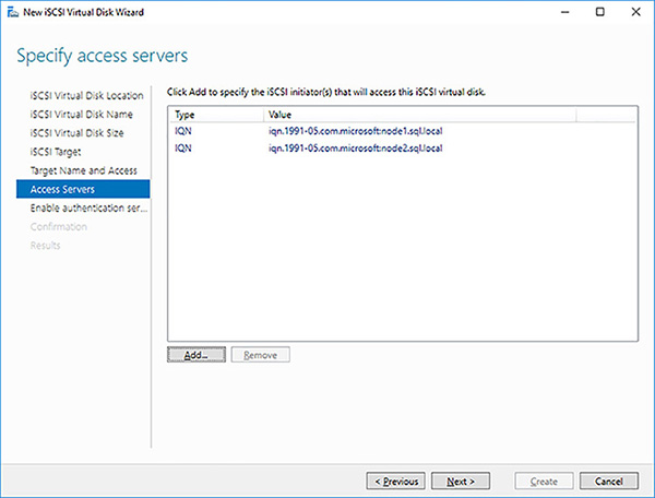
FIGURE 4-38 Availability Group Synchronous Commit
As there will be no authentication, click on the Next button in the Enable Authentication page.
Confirm the properties of the iSCSI virtual disk you are about to create, as shown in Figure 4-39 and click on the Create button.
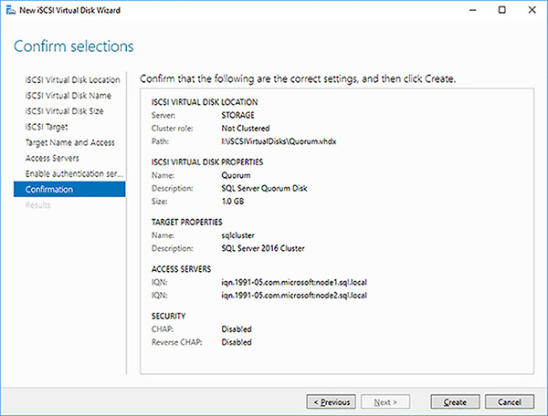
FIGURE 4-39 iSCSI virtual disk confirmation
Click on the Close button after the successful creation of your iSCSi virtual disk for the quorum disk of the failover cluster.
Repeat the above iSCSI virtual disk creation steps to create a 100GB thinly provisioned iSCSI disk for the databases’ data files.
Repeat the above iSCSI virtual disk creation steps to create a 50GB thinly provisioned iSCSI disk for the databases’ transaction log files.
Repeat the above iSCSI virtual disk creation steps to create a 20GB thinly provisioned iSCSI disk for the [tempdb] system database’s data files.
Repeat the above iSCSI virtual disk creation steps to create a 10GB thinly provisioned iSCSI disk for the [tempdb] system database’s transaction log.
In Server Manager, you should have 5 iSCSI virtual disks created for the failover cluster, as shown in Figure 4-40.
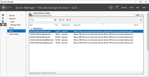
FIGURE 4-40 iSCSI disks configured for failover cluster
You need to configure the iSCSI Target Server to only communicate over the dedicated iSCSI network. In Server Manager click on Servers, then right-click on your storage server and select the iSCSI Target Settings option.
Select just the iSCSI network, as shown in Figure 4-41 and click on the OK button.
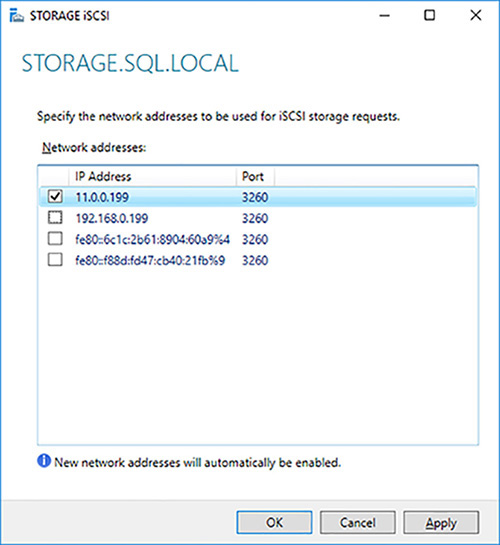
FIGURE 4-41 Isolating iSCSI traffic on dedicated network
)
)
)
)
You have now created 5 iSCSI LUNs for your failover cluster. You now need to configure your failover cluster. You need to perform the following high-level steps:
Install and configure the iSCSI Initiator on each Node that will be part of the failover cluster.
Format the iSCSI disks.
Install WSFC on all the Nodes that are going to be part of the failover cluster.
Create a failover cluster with all the Nodes.
Create a SQL Server FCI by installing it the first Node of the failover cluster.
Complete the installation of the SQL Server FCI by installing SQL Server on the additional Nodes of the failover cluster and joining the SQL Server FCI installed on the first Node.
The following steps show how to install and configure the iSCSI Initiator on each of the Nodes of the cluster.
Log into the first Node that will be part of your failover cluster.
Open Server Manager.
Select the iSCSI Initiator for the Tools menu.
Click on the Yes to confirm that you want the Microsoft iSCSI service to start automatically whenever the computer restarts.
Type in the name of your iSCSI target server into the Target text box and click on the Quick Connect button.
In the Quick Connect dialog box click on the Connect button and then the Done button so that the Node will be able to connect to the iSCSI Target Server LUNs as required.
Confirm that your Node is connected to the iSCSI target server you created earlier and click on the OK button, as shown in Figure 4-42.
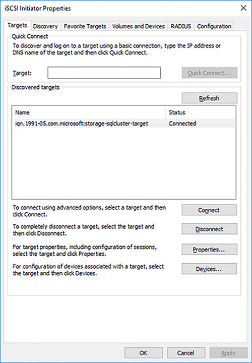
FIGURE 4-42 Successfully connect to iSCISI Target Server
Configure the iSCSI initiator on the other nodes that you plan to add to the failover cluster
The next step is to format the iSCSI disks using the following properties:
NTFS file system.
Although ReFS is supported, it not recommended for SQL Server database files due to performance reasons.
64KB allocation unit size.
The 1GB quorum disk can be formatted with the default (4KB) allocation unit size.
Do not allow the files on the drives to have their contents indexes in addition to file properties.
Assign the drive letters as per Table 4-4.
The following steps show how to format the iSCSI disks:
Log into the first Node that will be part of your failover cluster.
Open Disk Management.
Right click on the first iSCSI disk, which should be the 1GB quorum disk and click Online to bring it online.
Right-click on the same disk and select the Initialize Disk option.
In the Initialize Disk dialog box choose the MBR (Master Boot Record) option and click on the OK button.
In Disk Management, right click on the same disk and select the New Simple Volume option to format the disk.
In the New Simple Volume Wizard click on the Next button in the welcome screen.
In the Specify Volume Size page click on the Next button to format the simple volume with the default maximum possible disk size.
In the Assign Drive Letter Or Path screen choose the Do Not Assign A Drive Letter Or Drive path option. The quorum disk for the failover cluster does not require a drive letter to work.
Configure the format settings for the quorum disk and click on the Next button.
For a production environment, you should normally perform a full format to maximize performance and ensure there is no storage problems.
For your lab or development environment you should perform a quick format so as to save actual disk space.
Review the disk format settings and click on the Finish button to format the disk.
Format the remaining disks using the same steps as above. Remember to format the disks using the NTFS file system and 64KB allocation unit size. Use Figure 4-43 as a guide for the drive letters and volume names.
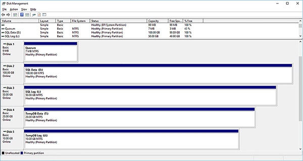
FIGURE 4-43 Failover cluster formatted volumes
)
)
You can now set up the failover cluster that the SQL Server FCI will be using. The first step is to install WSFC on all of the Nodes of the failover cluster.
Use the following steps to install WSFC on the first node of your failover cluster.
Open up Server Manager on the first Node.
Choose Add Roles And Features from the Manage drop-down list.
In the Add Roles And Features Wizard click on the Next button.
Choose the Role-Based Or Feature-Based Installation and click on Next.
Ensure your local server is selected in the Server Pool and click on the Next button.
Do not install any roles. Click on the Next button in the Select Server Roles page.
Select the Failover Clustering check box to install the Failover Clustering feature.
The Add Roles And Features Wizard will, by default, want to install the Failover Clustering tools and Powershell modules. Confirm this action by clicking on the Add Features button.
Confirm that you are installing Failover Clustering and the related tools before clicking on the Install button to begin the installation.
Confirm the installation was successful and click on the on the Close button to finish.
Repeat the WSFC installation on the other Nodes in the failover cluster using the same steps.
After installing the WSFC on all of the Nodes of your failover cluster you are reading to create the cluster. To install a failover cluster, you will need to have rights to modify your AD environment. Consequently, you will need to do one of the following:
Log in as Domain Administrator when creating the failover cluster.
Log in as yourself and get the Domain Administrator to run the setup executables as themselves using the Run As capability in the Windows OSE.
Get the Domain Admin to pre-stage the cluster computer objects in Active Directory Domain Services as described in https://technet.microsoft.com/en-us/library/dn466519(v=ws.11).aspx.
The following steps show how to create a failover cluster.
Log into your Node as the Domain Administrator.
Open Failover Cluster Manager, which has now been installed on your server.
Click on the Create Cluster action in the right-most pane. This will start the Create Cluster Wizard.
Click on the Next button in the Before You Begin page of the Create Cluster Wizard.
Enter the name of the first Node that you want to add to the failover cluster and click on the Add button. The Create Cluster Wizard will validate the server’s existence and add it to the bottom text box using its fully qualified domain name (FQDN).
Add all the nodes to you cluster, then click on the Next button as shown in Figure 4-44.
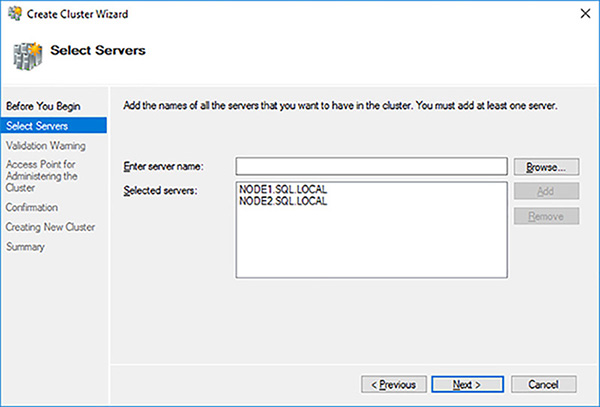
FIGURE 4-44 Selected nodes for failover cluster
You need to validate that your nodes are capable of running a failover cluster that will be supported by Microsoft. Click on the Next button to run the configuration validation tests.
The Validate A Configuration Wizard will by default automatically run all of the appropriate cluster validation tests for you. Click on the Next button in the Validate A Configuration Wizard.
It is a best practice to run all the cluster validation tests. Click on the Next button to start the validation tests, as shown in Figure 4-45.
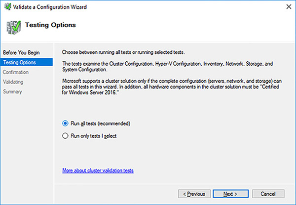
FIGURE 4-45 Running all cluster validation tests
Figure 4-46 shows you what tests will be run by default. Note that the Storage Space Direct tests will not be run because you have not installed and configured this feature.
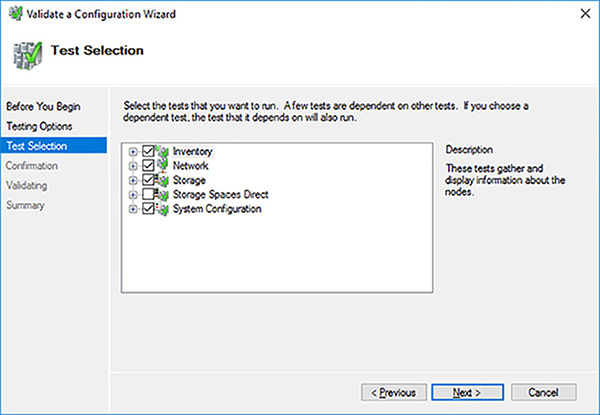
FIGURE 4-46 Possible cluster validation tests
Review the servers to test and the tests that will be run. Click on the Next button to start the failover cluster validation tests. Figure 4-47 shows the cluster validation tests performing disk failover tests, which are critical to a failover cluster. Note the SCSI-3 persistent reservations tests, and another critical test was successful.
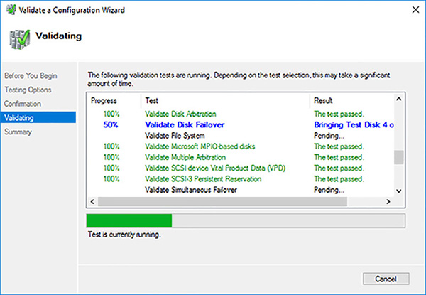
FIGURE 4-47 Cluster validation tests executing disk failover tests
Wait for the cluster validation tests to complete. It is not uncommon to have warnings, such as that software patches might be missing. You can fix any issues and re-run the cluster validation issues if that is warranted. Click on the View Report button to see if there are any serious issues.
Review the Failover Cluster Validation Report, shown in Figure 4-48. It is a phenomenally good practice to keep it for support reasons.
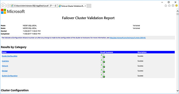
FIGURE 4-48 Successful failover cluster validation report
Close the report when you have completed your review.
Click on the Finish button to close the Validate A Configuration Wizard.
Provide a computer name and IP address for the Client Access Point (CAP), as shown in Figure 4-49, and click on the Next button. The CAP is used to manage the cluster.
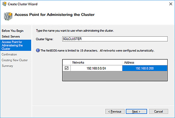
FIGURE 4-49 Client Access Point configuration
Check the Add All Eligible Storage To The Cluster option, review and confirm the creation of the failover cluster by clicking on the Next button.
Wait for the failover cluster to be created. Figure 4-50 shows one of the most important steps, where the Computer Name Object (CNO) is created in Active Directory (AD).
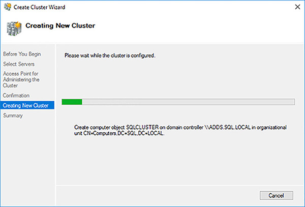
FIGURE 4-50 Creating CNO in AD for failover cluster
Review the failover cluster creation Summary page. Click on the View Report button to view the detailed failover cluster creation report.
Review and save the Create Cluster report, shown in Figure 4-51, looking out for any errors and warnings.
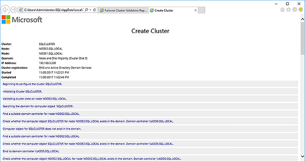
FIGURE 4-51 Create Cluster report
)
)
)
)
)
)
)
)
Your failover cluster should now be created. Before you install the SQL Server FCI it is a good idea to change a few elements in your failover cluster to ensure optimal operation and make it easier to manage.
Perform the following steps:
In Failover Cluster Manager connect to your failover cluster.
Click on the Networks folder.
The default configuration is for the networks to be serially identified. It is a best practice to rename them to help troubleshoot and administer your failover cluster correctly. Furthermore, the default is to send cluster traffic across all three networks. In this case, you do no not want cluster traffic to be sent across the iSCSI network. You want it purely for our iSCSI storage traffic.
Right-click on Cluster Network 1 (192.168.0.0) and select its properties. Change its properties as shown below:
Name: Public Network
Allow cluster network communication on this network
Allow clients to connect through this network
Right click on Cluster Network 2 (10.0.0.0) and select its properties. Change its properties as shown below:
Name: Private Network
Allow cluster network communication on this network
Right click on Cluster Network 1 (11.0.0.0) and select its properties. Change its properties as shown below:
Name: iSCSI Network
Do not allow cluster network communication on this network
Make sure you cluster networks have been reconfigured as shown in Figure 4-52
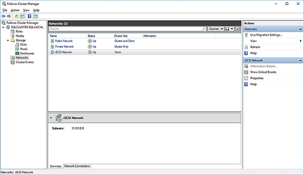
FIGURE 4-52 Re-configured cluster networks
Click on the Disks folder. All of the disks have also been named serially. Again, it is a best practice to rename them to help administration and minimize mistakes.
Right-click on the 1GB cluster disk being used as a disk witness and select Properties.
Rename the cluster disk to “Quorum Disk” to indicate its purpose.
Rename all cluster disks, as shown in Figure 4-53, to match their intended purpose.
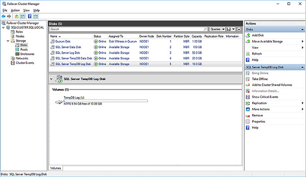
FIGURE 4-53 Renamed cluster disks
)
)
Finally, you are ready to install the SQL Server FCI. The process to create SQL Server FCI involves:
Run the SQL Server setup on the first node to install a SQL Server FCI on the first node
Run the SQL Server setup on the second node to join it to the SQL Server FCI
Use the following steps to install start the installation of the SQL Server FCI on the failover cluster:
Log into Node 1 of the failover cluster as an administrator.
Mount the SQL Server Developer ISO and run the setup program.
Click on the Installation link in the SQL Server Installation Center.
Click on the New SQL Server Failover Cluster Installation link, as shown in Figure 4-54, to start the Install A SQL Server Failover Cluster setup.
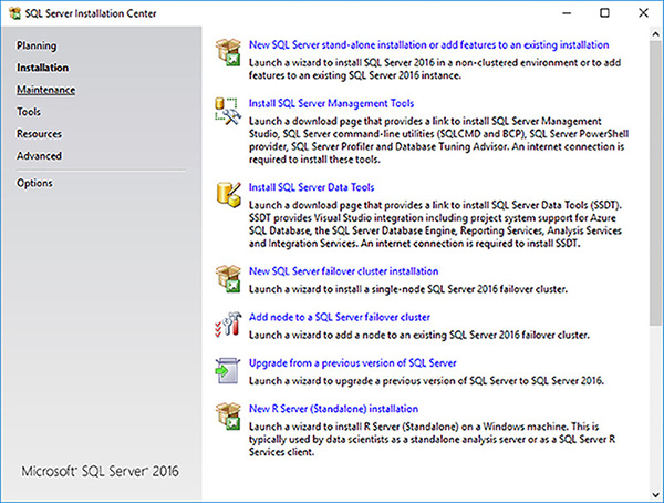
FIGURE 4-54 New SQL Server failover cluster installation
In the Product Key page of the Install A SQL Server Failover Cluster setup enter the product key to specify a free edition.
In the License Terms page accept the license terms and click on the Next button.
In the Global Rules page let the setup engine check to see if there are any blockers for the installation and click on the Next button.
In the Microsoft Update page, you can let the setup process check for important updates. Don’t. It’s easier to manually install any updates. Click on the Next button.
Click on the Next button in the Product Updates page.
The Install Failover Cluster Rules page, shown in Figure 4-55, runs a number of checks to see if anything would block the FCI install. Review warnings and correct any errors as required. In this case, it is passing through the warning generated by the failover cluster validation done earlier. Click on the Next button when you are ready to proceed to the next step.
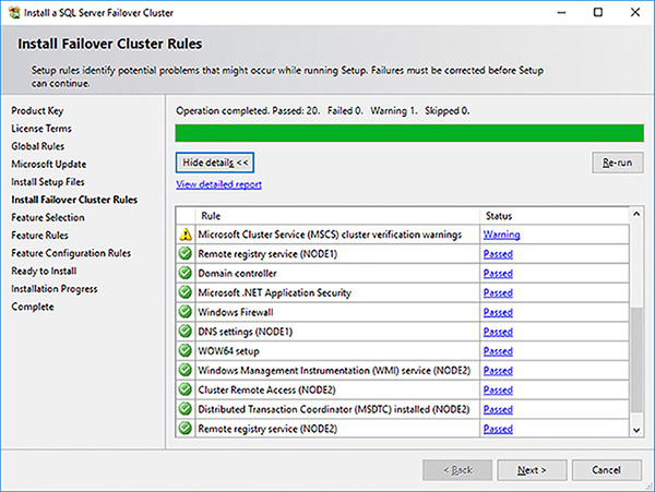
FIGURE 4-55 SQL Server FCI setup install failover cluster rules
In the Feature Selection page, shown in Figure 4-56, select the appropriate features. When installing a SQL Server FCI consider the following.
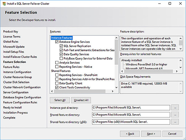
FIGURE 4-56 SQL Server FCI setup feature selection
The setup process will automatically install the SQL Server Replication, Full-Text, and Semantic Extractions for Search and Data Quality Services.
SSRS is not cluster aware.
SSIS is not cluster aware.
Consider installing SSAS as a separate FCI.
In the Instance Configuration page provide a name for the SQL Server instance, as shown in Figure 4-57 and click on the Next button. In a WSFC you can only install a single default instance. It will be access via its network name. All subsequent instances will be named instances that can be accessed via their network name\instance name.
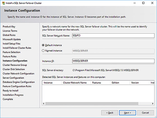
FIGURE 4-57 SQL Server FCI setup instance configuration
In the Cluster Resource Group provide a name for the SQL Server Cluster Resource Group name, as shown in Figure 4-58, and click on the Next button. Consider having a naming standard if you plan to install multiple SQL Server FCIs in a failover cluster.
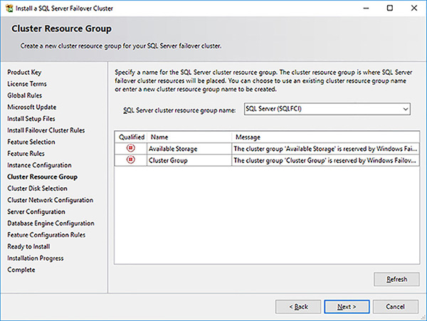
FIGURE 4-58 SQL Server FCI setup cluster resource group
Select the cluster disks that your SQL Server FCI will use in the Cluster Disk Selection page, as shown in Figure 4-59, and click on the Next button. Note the benefit of renaming the cluster disks in the failover cluster earlier.
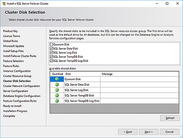
FIGURE 4-59 SQL Server FCI setup cluster disk selection
Provide an IP address in the Cluster Network Configuration page, as shown in Figure 4-60,s and click on the Next button.
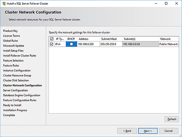
FIGURE 4-60 SQL Server FCI setup cluster network configuration
Enter the service account and password details, as shown in Figure 4-61.
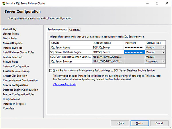
FIGURE 4-61 SQL Server FCI setup service accounts
Click on the Collation tab, and enter the required collation.
Click on the Next button.
In the Database Engine Configuration page configure the Server Configuration details, as shown in Figure 4-62.
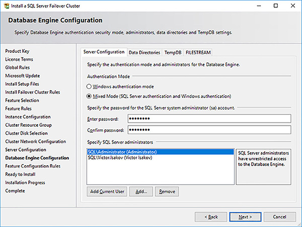
FIGURE 4-62 SQL Server FCI setup server configuration
Click on the Data Directories tab and configure the paths for the database and backup paths, as shown in Figure 4-63.
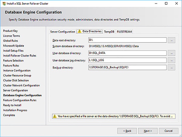
FIGURE 4-63 SQL Server FCI setup data directories
Click on the TempDB tab and configure the paths for the [tempdb] system database, as shown in Figure 4-64.
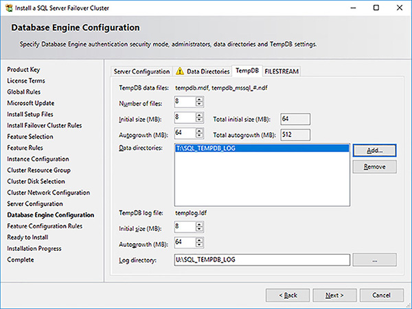
FIGURE 4-64 SQL Server FCI setup TempDB configuration
Click on the FILESTREAM tab and configure your filestream options before clicking on the Next button.
In the Feature Configuration Rules page, as shown in Figure 4-65, let the setup engine run its checks and click on the Next button.
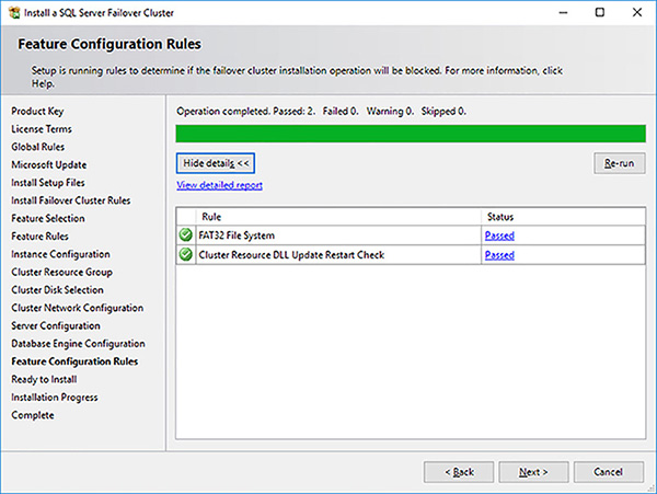
FIGURE 4-65 SQL Server FCI setup feature configuration rules
Review the summary of your SQL Server FCI setup and click on the Install button to initiate the installation procedure.
Once the setup has completed, review the summary to ensure nothing has gone wrong. Save the summary log for support reasons and click on the Close button to complete close the installer.
)
)
)
)
)
)
)
)
)
)
)
)
You now need to complete the installation of the SQL Server FCI by installing the same configuration on the second Node. Fortunately, this is a lot easier as the installation on the first node has most of the information needed to complete the installation on the second Node, barring the service account passwords.
Use the following steps to complete the installation of the SQL Server FCI on the failover cluster:
Log into Node 2 of the failover cluster as an administrator.
Mount the SQL Server Developer ISO and run the setup program.
Click on the Installation link in the SQL Server Installation Center.
Click on the Add Node To A SQL Server Failover Cluster link, as shown in Figure 4-54, to start the Install A SQL Server Failover Cluster setup.
In the Product Key page of the Install A SQL Server Failover Cluster setup enter the product key to specify a free edition, like for Node 1, and click on the Next button.
In the License Terms page accept the license term and click on the Next button.
In the Global Rules page let the installer check to see if there are any blockers for the installation and click on the Next button.
In the Microsoft Update page, like for Node 1, click on the Next button for Node 1.
Click on the Next button in the Product Updates page, for Node 1.
In the Install Setup Files page let the installer install the required setup files and click on the Next button.
The Add Node Rules page, shown in Figure 4-66, runs a number of checks to see if anything would block the Node being added to the FCI. Review and warnings and correct any errors as required. Click on the Next button when you are done.
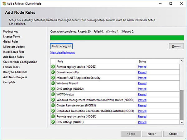
FIGURE 4-66 SQL Server FCI setup install add node rules
In the Cluster Node Configuration page, shown in Figure 4-67, the installer shows you details of the SQL Server FCI you are going to become part of. Remember that you can have multiple SQL Server FCIs in a failover cluster. In this case, there is only one SQL Server FCI. Click on the Next button when you have reviewed the page.
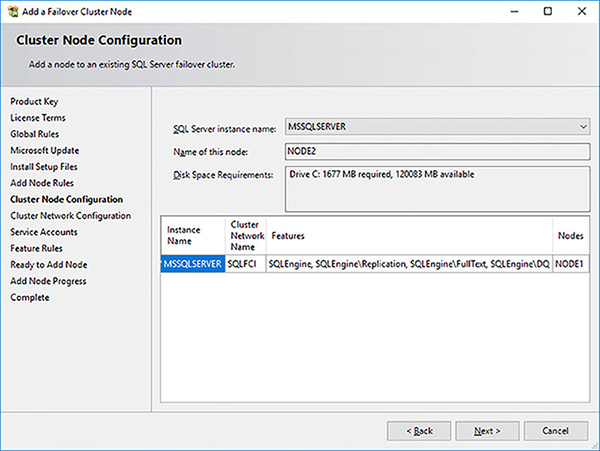
FIGURE 4-67 SQL Server FCI setup cluster node configuration
In the Cluster Network Configuration page the installer shows you details of the SQL Server FCI’s network configuration Click on the Next button.
In the Service Accounts page provide the same passwords for the credentials configured for Node 1 and click on the Next button.
You should ensure that you have configured the Grant Perform Volume Maintenance Task Privilege To SQL Server Database Engine Service all Nodes of the failover cluster.
The Feature Rules page, shown in Figure 4-197, checks to see if there are any blocking processes for configuring the SQL Server FCI. Click on the Next button to proceed to the next step.
In the Ready To Add Node page review what will be installed and click on the Install button to engage the completion of the SQL Server FCI installation.
Save the setup log for support reasons and click on the Close button.
)
)
In general, there is nothing further to configure after you create your SQL Server FCI. However, you should familiarize yourself with the failover cluster and SQL Server FCI, especially if they have been deployed using new versions of Windows Server and SQL Server.
Figure 4-68 shows the SQL Server FCI that you have created. The bottom pane shows all the resources of the SQL Server FCI.
)
FIGURE 4-68 SQL Server FCI resources
To see the dependencies between these resources, perform the following steps:
Open Failover Cluster Manager.
Connect to your failover cluster.
Click on the Roles folder.
Right-click on your SQL Server FCI and click on the More Actions menu option.
Select the Show Dependency Report.
The SQL Server FCI Dependency Report will be shown in a web browser. Scroll down the report until you see the graphical representation of the dependencies between the various cluster resource of your SQL Server FCI, as shown in Figure 4-69. Note, for example, how the SQL Server Agent can’t be brought online until the SQL Server Database Engine is online. Also note how all the physical disks have to be brought online with the Network Name before SQL Server can be started.
)
FIGURE 4-69 SQL Server FCI dependency report
You might have noticed from the above figures above that there is a new resource that gets installed with a SQL Server 2016 FCI, the SQL Server CEIP. Figure 4-70 shows the SQL Server CEIP cluster resource properties.
)
FIGURE 4-70 SQL Server CEIP resource properties
The SQL Server CEIP is the telemetry service that gets installed now by default with SQL Server 2016 and by default automatically transmits information about your installation experience, as well as other usage and performance, to Microsoft.
Configure Quorum Configuration
Quorum in a failover cluster is how the various elements of your WSFC vote to decide whether a SQL Server FCI can be started or failed over. The concept of quorum in your WSFC is critical to the functioning of your SQL Server FCIs. Without quorum, the WSFC will go offline as a precautionary measure and your SQL Server FCIs will also be taken offline.
The quorum configuration controls what different elements can participate in the decision as to whether a WSFC can form quorum. Typically, all Nodes in your failover cluster will have a vote in the quorum. You can add additional quorum witnesses to help form quorum and avoid the “split brain” problem, where there is not a majority of votes formed. In general, you want to have an odd number of voters in your WSFC configuration.
Figure 4-71 shows how you can control what Nodes of your failover cluster can participate in the quorum voting. In certain cases, as we saw with Availability Groups, you might not want a Node to have a vote in your quorum. With a Node witness, each Node has the cluster database located locally. When a change is made to the failover cluster is it considered committed when it has been applied to the local cluster database on behalf of the Nodes (rounding down) plus one.
)
FIGURE 4-71 Configuration of voting nodes for quorum
You can add additional witness voters to the Node voters in your WSFC. This can help ensure that you have an odd number of voters in your quorum configuration. It also allows you to correctly place the witness in your existing infrastructure.
Generally, you should always configure a witness. Since Windows Server 2012 failover clustering has supported dynamic quorum, and thus dynamic witnesses. Dynamic quorum modifies the vote allocation to nodes dynamically in your failover cluster, as circumstances change, as in the case of 2 nodes in a 5 node failover cluster being shut down. With a dynamic witness, if there is an odd number of votes, the quorum witness does not have a vote. If there is an even number of votes, the quorum witness has a vote.
If you are using shared storage, you can take advantage of a disk witness. A disk witness is a dedicated LUN that stores a copy of the cluster database. Figure 4-72 shows the configuration for the disk witness. Always try to use a disk witness over other witness in the case where you are using shared storage in your failover cluster, as it is more robust than other types of witnesses. Remember that a disk witness LUN does not require a drive letter. A disk witness only needs 512MB of disk storage.
)
FIGURE 4-72 Configuration of disk witness in WSFC
Figure 4-73 shows the file share witness option. In the case of a file share witness the cluster database is not stored there. The file share witness only keeps track of which Node has the most updated cluster database in the witness.log file. This can lead to a scenario where only a single Node and the file share witness survive, but the failover cluster will not be able to come online if the surviving node does not have the most up to date version of the cluster database because this would cause a “partition in time.” That is why the disk witness was recommended over the file share witness. You should use the file share witness when you do not have shared storage or where you have a multisite cluster with replicated storage.
)
FIGURE 4-73 Configuration of file share witness in WSFC
Figure 4-74 shows the cloud witness, which was added with Windows Server 2016. It is fundamentally a file share witness, except that it is hosted in Microsoft Azure. Its primary use case is where you have two data centers and ideally need to place the witness in a third data center.
)
FIGURE 4-74 Configuration of cloud witness in WSFC
Manage Shared Disks
Disks (LUNs) attached to a failover cluster work differently from disks attached to a stand-alone server environment. A number of health monitoring checks are performed on a failover cluster managed disks. If any of these checks fail the WSFC will assume there is a problem and take appropriate action, including:
Try to restart the resources and mount the disk on same node.
Assume failover ownership of the disk.
Try to bring the disk online on another Node.
The following file system level checks are performed on disks managed by WSFC:
LooksAlive A quick check is performed every 5 seconds to verify the disk is still available.
IsAlive A complete check is performed every 60 seconds to verify the disk and the file system can be accessed.
Additionally, the following device level checks are performed by the Clusdisk.sys driver:
SCSI Reserve A SCSI Reserve command is sent to the LUN every 3 seconds to ensure that only the owning node has ownership and can access the disk.
Private Sector Perform a read/write operation to sector 12 of the LUN every 3 seconds to ensure that the device is writable.
Sometimes you need to perform certain administrative or maintenance tasks on your clustered disks that require exclusive access to the disk, such as with the CHKDSK/F or FORMAT operations. In such cases, you do not the health monitoring checks to fail and trigger a failover.
To perform such administrative or maintenance tasks on your failover cluster’s shared disks you first need to place the disk into maintenance mode. This can be done in Failover Cluster Manager by right clicking on the disk, selecting More Actions and then Turn On Maintenance Mode.
Configure Cluster Shared Volumes
Clustered Shared Volumes (CSV) is a new clustered file system in Windows Server that is a layer of abstraction above the NTFS file system in a WSFC environment. It allows all Nodes in the failover cluster to read and write to the CSV volume. CSV leverages the investments Microsoft have made in SMB 3.0, such as SMB Direct and SMB Multichannel.
SQL Server 2014 was the first version of SQL Server to support CSVs. However, CSVs are not commonly deployed with SQL Server in the industry. This poor adoption is mostly like due to a lack of awareness in the industry of CSV and its related benefits.
The Cluster Shared Volume architecture, shown in Figure 4-75, contains the following elements:
Coordinator Node The Coordinator node is the node of your failover cluster on which the NTFS volume is mounted. All meta data operations from the other nodes in your failover cluster are orchestrated through this coordinator node using SMB 3.0. Meta data operations in SQL Server include opening and closing a database, creating a database, and auto-growing a database. Such meta data operations are relatively rare.
CSV Proxy File System The CSV Proxy File System is mounted on all nodes of the failover cluster. All read and write operations are sent directly through these proxies to the shared storage. This direct I/O is not even hitting the NTFS stack. If a Node cannot communicate directly to the shared storage it can communicate with the CSV Proxy File System using SMB 3.0 at the block level.
CSVFS The Clustered Share Volume File System (CSVFS) is the clustered file system that spans all nodes of the failover cluster. It is effectively the layer of abstraction that sits on top of the NTFS file system.
NTFS Stack The NTFS stack is used for all meta data operations to maintain consistency at the file system level.
)
FIGURE 4-75 Cluster Share Volumes architecture
The benefits of CSV include:
Faster failover times because there are no physical disks that need to be unmounted/mounted by the WSFC.
Improved resilience in the case a data path fails. A Node is now able to redirect its block level I/O to the coordinator node. With the benefits of SMB 3.0, including SMB multichannel and SMB Direct (RDMA), there should be no/minimal performance impact.
Your failover cluster no longer relies upon drive letters. You can only have as many cluster disks as the alphabet allows (24 in most cases). In the case of CSVs you are no longer replying on drive letters.
Zero downtime with CHKDSK operations. Effectively you can provide disk repairs without any SQL Server down time.
Easier administration as you are able to manage the underlying storage from any node. CSVFS provides the same abstraction layer across all nodes of the failover cluster.
The following steps show you have to implement CSVs in your SQL Server FCI.
Log into your storage server as administrator.
Provision another 2 iSCSI virtual disks as your iSCSI targets.
Log into Node 1 of the failover cluster as an administrator.
Open Disk Management.
Online, initialize and format the two new disks as NTFS volumes.
Open Failover Cluster Manager and connect to your failover cluster.
Right-click on the Disks folder and select the Add Disk option.
Select both new disks in the Add Disks To A Cluster dialog box and click on the OK button.
Rename both new cluster disks to something more meaningful.
Convert the cluster disks to Cluster Shared Volumes by right clicking on each cluster disk and selecting the Add To Cluster Shared Volumes option.
Confirm that the disks are not Cluster Shared Volumes and the they are using the CSVFS filesystem, as shown in Figure 4-76.
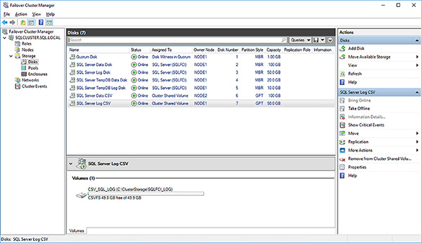
FIGURE 4-76 Cluster Shared Volumes and CSVFS filesystem
Open File Explorer and navigate to the C:\ClusterStorage root CSV folder as shown in Figure 4-77.
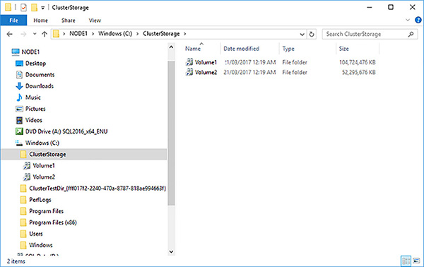
FIGURE 4-77 C:\ClusterStorage root CSV location
Rename the two volume folders to something more meaningful.
Create a subdirectory under both mount points for the SQL Server FCI to store the database files.
Open SQL Server Management Studio and connect to the SQLFCI instance.
Create a new database using the CSV database paths, as shown in Figure 4-78.
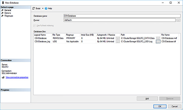
FIGURE 4-78 CSV database paths for SQL Server FCI
Switch to File Explorer and confirm the database files have been created in the CSV folder namespace.
Log into Node 2 of your failover cluster.
Open File Explorer and navigate to the same directory location used in Step 16.
Confirm you can see the database files there as well.
Switch back to Node 1.
Switch back to Failover Cluster Manager.
Generate a new Dependency Report.
Confirm you cannot see the CSVs in the dependencies, unlike the physical disks.
)
)
)
Consider using CSVs in your next SQL Server 2016/2017 failover cluster solution because they offer a number of advantages over traditionally deployed shared disks.