Understanding the Windows I/O System
- By Mark E. Russinovich, Kate Chase, Alex Ionescu
- 9/15/2012
The Power Manager
Just as Windows Plug and Play features require support from a system’s hardware, its power-management capabilities require hardware that complies with the Advanced Configuration and Power Interface (ACPI) specification (available at http://www.acpi.info).
The ACPI standard defines various power levels for a system and for devices. The six system power states are described in Table 8-8. They are referred to as S0 (fully on or working) through S5 (fully off). Each state has the following characteristics:
Power consumption The amount of power the computer consumes
Software resumption The software state from which the computer resumes when moving to a “more on” state
Hardware latency The length of time it takes to return the computer to the fully on state
States S1 through S4 are sleeping states, in which the computer appears to be off because of reduced power consumption. However, the computer retains enough information, either in memory or on disk, to move to S0. For states S1 through S3, enough power is required to preserve the contents of the computer’s memory so that when the transition is made to S0 (when the user or a device wakes up the computer), the power manager continues executing where it left off before the suspend.
Table 8-8 System Power-State Definitions
State |
Power Consumption |
Software Resumption |
Hardware Latency |
S0 (fully on) |
Maximum |
Not applicable |
None |
S1 (sleeping) |
Less than S0, more than S2 |
System resumes where it left off (returns to S0) |
Less than 2 seconds |
S2 (sleeping) |
Less than S1, more than S3 |
System resumes where it left off (returns to S0) |
2 or more seconds |
S3 (sleeping) |
Less than S2; processor is off |
System resumes where it left off (returns to S0) |
Same as S2 |
S4 (hibernating) |
Trickle current to power button and wake circuitry |
System restarts from saved hibernatation file and resumes where it left off prior to hibernation (returns to S0) |
Long and undefined |
S5 (fully off) |
Trickle current to power button |
System boot |
Long and undefined |
When the system moves to S4, the power manager saves the compressed contents of memory to a hibernation file named Hiberfil.sys, which is large enough to hold the uncompressed contents of memory, in the root directory of the system volume. (Compression is used to minimize disk I/O and to improve hibernation and resume-from-hibernation performance.) After it finishes saving memory, the power manager shuts off the computer. When a user subsequently turns on the computer, a normal boot process occurs, except that Bootmgr checks for and detects a valid memory image stored in the hibernation file. If the hibernation file contains saved system state, Bootmgr launches Winresume, which reads the contents of the file into memory, and then resumes execution at the point in memory that is recorded in the hibernation file.
On systems with hybrid sleep enabled (by default, only desktop computers), a user request to put the computer to sleep will actually be a combination of both the S3 state and the S4 state: while the computer is put to sleep, an emergency hibernation file will also be written to disk. Unlike typical hibernation files, which contain almost all active memory, the emergency hibernation file includes only data that could not be paged in at a later time, making the suspend operation faster than a typical hibernation (because less data is written to disk). Drivers will then be notified that an S4 transition is occurring, allowing them to configure themselves and save state just as if an actual hibernation request had been initiated. After this point, the system is put in the normal sleep state just like during a standard sleep transition. However, if the power goes out, the system is now essentially in an S4 state—the user can power on the machine, and Windows will resume from the emergency hibernation file.
The computer never directly transitions between states S1 and S4; instead, it must move to state S0 first. As illustrated in Figure 8-45, when the system is moving from any of states S1 through S5 to state S0, it’s said to be waking, and when it’s transitioning from state S0 to any of states S1 through S5, it’s said to be sleeping.
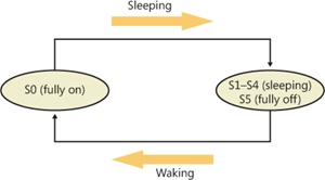
Figure 8-45 System power-state transitions
Although the system can be in one of six power states, ACPI defines devices as being in one of four power states, D0 through D3. State D0 is fully on, and state D3 is fully off. The ACPI standard leaves it to individual drivers and devices to define the meanings of states D1 and D2, except that state D1 must consume an amount of power less than or equal to that consumed in state D0, and when the device is in state D2, it must consume power less than or equal to that consumed in D1. Microsoft, in conjunction with the major hardware OEMs, has defined a series of power management reference specifications that specify the device power states that are required for all devices in a particular class (for the major device classes: display, network, SCSI, and so on). For some devices, there’s no intermediate power state between fully on and fully off, which results in these states being undefined.
Power Manager Operation
Power management policy in Windows is split between the power manager and the individual device drivers. The power manager is the owner of the system power policy. This ownership means that the power manager decides which system power state is appropriate at any given point, and when a sleep, hibernation, or shutdown is required, the power manager instructs the power-capable devices in the system to perform appropriate system power-state transitions. The power manager decides when a system power-state transition is necessary by considering a number of factors:
System activity level
System battery level
Shutdown, hibernate, or sleep requests from applications
User actions, such as pressing the power button
Control Panel power settings
When the PnP manager performs device enumeration, part of the information it receives about a device is its power-management capabilities. A driver reports whether or not its devices support device states D1 and D2 and, optionally, the latencies, or times required, to move from states D1 through D3 to D0. To help the power manager determine when to make system power-state transitions, bus drivers also return a table that implements a mapping between each of the system power states (S0 through S5) and the device power states that a device supports.
The table lists the lowest possible device power state for each system state and directly reflects the state of various power planes when the machine sleeps or hibernates. For example, a bus that supports all four device power states might return the mapping table shown in Table 8-9. Most device drivers turn their devices completely off (D3) when leaving S0 to minimize power consumption when the machine isn’t in use. Some devices, however, such as network adapter cards, support the ability to wake up the system from a sleeping state. This ability, along with the lowest device power state in which the capability is present, is also reported during device enumeration.
Table 8-9 Example System-to-Device Power Mappings
System Power State |
Device Power State |
S0 (fully on) |
D0 (fully on) |
S1 (sleeping) |
D1 |
S2 (sleeping) |
D2 |
S3 (sleeping) |
D2 |
S4 (hibernating) |
D3 (fully off) |
S5 (fully off) |
D3 (fully off) |
Driver Power Operation
When the power manager decides to make a transition between system power states, it sends power commands to a driver’s power dispatch routine. More than one driver can be responsible for managing a device, but only one of the drivers is designated as the device power-policy owner. This driver determines, based on the system state, a device’s power state. For example, if the system transitions between state S0 and S1, a driver might decide to move a device’s power state from D0 to D1.
Instead of directly informing the other drivers that share the management of the device of its decision, the device power-policy owner asks the power manager, via the PoRequestPowerIrp function, to tell the other drivers by issuing a device power command to their power dispatch routines. This behavior allows the power manager to control the number of power commands that are active on a system at any given time. For example, some devices in the system might require a significant amount of current to power up. The power manager ensures that such devices aren’t powered up simultaneously.
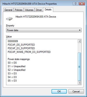
EXPERIMENT: Viewing a Driver’s Power Mappings
You can see a driver’s system power state to driver power state mappings with Device Manager. Open the Properties dialog box for a device, and choose the Power Data entry in the drop-down list on the Details tab to see the mappings.
The dialog box also displays the current power state of the device, the device-specific power capabilities that it provides, and the power states from which it is able to wake the system.
Many power commands have corresponding query commands. For example, when the system is moving to a sleep state, the power manager will first ask the devices on the system whether the transition is acceptable. A device that is busy performing time-critical operations or interacting with device hardware might reject the command, which results in the system maintaining its current system power-state setting.
EXPERIMENT: Viewing the System Power Capabilities and Policy
You can view a computer’s system power capabilities by using the !pocaps kernel debugger command. Here’s the output of the command when run on an ACPI-compliant laptop:
lkd> !pocaps
PopCapabilities @ 0x82114d80
  Misc Supported Features:  PwrButton SlpButton Lid S3 S4 S5 HiberFile
   FullWake
                            VideoDim
  Processor Features:       Thermal
  Disk Features:            SpinDown
  Battery Features:         BatteriesPresent
    Battery 0 - Capacity:        0  Granularity:        0
    Battery 1 - Capacity:        0  Granularity:        0
    Battery 2 - Capacity:        0  Granularity:        0
  Wake Caps
    Ac OnLine Wake:         Sx
    Soft Lid Wake:          Sx
    RTC Wake:               S4
    Min Device Wake:        Sx
    Default Wake:           Sx
The Misc Supported Features line reports that, in addition to S0 (fully on), the system supports system power states S1, S3, S4, and S5 (it doesn’t implement S2) and has a valid hibernation file to which it can save system memory when it hibernates (state S4).
The Power Options page, shown here (available by selecting Power Options in Control Panel), lets you configure various aspects of the system’s power policy. The exact properties you can configure depend on the system’s power capabilities, which we just examined.
)
By changing any of the preconfigured plan settings, you can set the idle detection timeouts that control when the system turns off the monitor, spins down hard disks, goes to standby mode (moves to system power state S1), and hibernates (moves the system to power state S4). In addition, selecting the Change Plan Settings option lets you specify the power-related behavior of the system when you press the power or sleep buttons or close a laptop’s lid.
)
The settings you configure by clicking the Change Advanced Power Settings link directly affect values in the system’s power policy, which you can display with the !popolicy debugger command. Here’s the output of the command on the same system:
lkd> !popolicy
SYSTEM_POWER_POLICY (R.1) @ 0x82107994
  PowerButton:         Sleep  Flags: 00000000   Event: 00000000
  SleepButton:         Sleep  Flags: 00000000   Event: 00000000
  LidClose:            Sleep  Flags: 00000000   Event: 00000000
  Idle:                Sleep  Flags: 00000000   Event: 00000000
  OverThrottled:        None  Flags: 00000000   Event: 00000000
  IdleTimeout:           384  IdleSensitivity:        90%
  MinSleep:               S3  MaxSleep:               S3
  LidOpenWake:            S0  FastSleep:              S0
  WinLogonFlags:           1  S4Timeout:            fd20
  VideoTimeout:          300  VideoDim:                0
  SpinTimeout:           258  OptForPower:             0
  FanTolerance:            0% ForcedThrottle:          0%

  SpinTimeout:           258  OptForPower:             0
  MinThrottle:             0% DyanmicThrottle:      None
The first lines of the display correspond to the button behaviors specified on the Advanced Settings tab of Power Options, and on this system both the power and the sleep buttons put the computer in a sleep state, just as closing the lid does.
The timeout values shown at the end of the output are expressed in seconds and displayed in hexadecimal notation. The values reported here directly correspond to the settings you can see configured on the Power Options page. (The laptop is on battery.) For example, the video timeout is 300, meaning the monitor turns off after 300 seconds, or 5 minutes, and the hard disk spin-down timeout is 0x258, which corresponds to 600 seconds, or 10 minutes.
Driver and Application Control of Device Power
Besides responding to power manager commands related to system power-state transitions, a driver can unilaterally control the device power state of its devices. In some cases, a driver might want to reduce the power consumption of a device it controls when the device is left inactive for a period of time. Examples include monitors that support a dimmed mode and disks that support spin-down. A driver can either detect an idle device itself or use facilities provided by the power manager. If the device uses the power manager, it registers the device with the power manager by calling the PoRegisterDeviceForIdleDetection function.
This function informs the power manager of the timeout values to use to detect a device as idle and of the device power state that the power manager should apply when it detects the device as being idle. The driver specifies two timeouts: one to use when the user has configured the computer to conserve energy and the other to use when the user has configured the computer for optimum performance. After calling PoRegisterDeviceForIdleDetection, the driver must inform the power manager, by calling the PoSetDeviceBusy or PoSetDeviceBusyEx functions, whenever the device is active, and then register for idle detection again to disable and re-enable it as needed. The PoStartDeviceBusy and PoEndDeviceBusy APIs are available in newer versions of Windows as well, which simplify the programming logic required to achieve the behavior that’s desired.
Although a device has control over its own power state, it does not have the ability to manipulate the system power state or to prevent system power transitions from occurring. For example, if a badly designed driver doesn’t support any low-power states, it can choose to remain on or turn itself completely off without hindering the system’s overall ability to enter a low-power state—this is because the power manager only notifies the driver of a transition and doesn’t ask for consent.
Although drivers and the kernel are chiefly responsible for power management, applications are also allowed to provide their input. User-mode processes can register for a variety of power notifications, such as when the battery is low or critically low, when the laptop has switched from DC (battery) to AC (adapter/charger) power, or when the system is initiating a power transition. Just like drivers, however, applications cannot veto these operations, and they can have up to two seconds to clean up any state necessary before a sleep transition.
Power Availability Requests
Even though applications and drivers cannot veto sleep transitions that are already initiated, certain scenarios demand a mechanism for disabling the ability to initiate sleep transitions when a user is interacting with the system in certain ways. For example, if the user is currently watching a movie and the machine would normally go idle (based on a lack of mouse or keyboard input after 15 minutes), the media player application should have the capability to temporarily disable idle transitions as long as the movie is playing. You can probably imagine other power-saving measures that the system would normally undertake, such as turning off or even just dimming the screen, that would also limit your enjoyment of visual media. In legacy versions of Windows, SetThreadExecutionState was a user-mode API capable of controlling system and display idle transitions by informing the power manager that a user was still present on the machine, but this API did not provide any sort of diagnostic capabilities, nor did it allow sufficient granularity for defining the availability request. Also, drivers were not able to issue their own requests, and even user applications had to correctly manage their threading model, because these requests were at the thread level, not at the process or system level.
Windows now supports power request objects, which are implemented by the kernel and are bona-fide object manager–defined objects. You can use the WinObj utility that was introduced in Chapter 3 in Part 1 and see the PowerRequest object type in the \ObjectTypes directory, or use the !object kernel debugger command on the \ObjectTypes\PowerRequest object type, to validate this. Power availability requests are generated by user-mode applications through the PowerCreateRequest API and then enabled or disabled with the PowerSetRequest and PowerClearRequest APIs, respectively. In the kernel, drivers use PoCreatePowerRequest, PoSetPowerRequest, and PoClearPowerRequest. Because no handles are used, PoDeletePowerRequest is implemented to remove the reference on the object (while user mode can simply use CloseHandle).
There are three kinds of requests that can be used through the Power Request API: a system request, a display request, and an “away-mode” request. The first type requests that the system not automatically go to sleep due to the idle timer (although the user can still close the lid to enter sleep, for example), while the second does the same for the display. “Away-mode” is a modification to the normal sleep (S3 state) behavior of Windows, which is used to keep the computer in full powered-on mode but with the display and sound card turned off, making it appear to the user as though the machine is really sleeping. This behavior is normally used only by specialized set-top boxes or media center devices when media delivery must continue even though the user has pressed a physical sleep button, for example. In the future, Windows may support other requests as well.
EXPERIMENT: Viewing a Power Availability Request in the Debugger
Because power availability requests are objects managed by the object manager, applications have handles open to them when calling the PowerCreateRequest API, and Process Explorer is able to find these handles by using the Search DLL/Handle functionality that was introduced in previous chapters.
You can search for “PowerRequest” and find certain services and applications on your machine that have made availability requests. (Drivers will not show up because the kernel API does not use handles.) For example, the Print Spooler (Spoolsvc.exe) and Windows Media Player Network Sharing Service (Wmpntwk.exe) are two Windows services that have availability request objects.
By launching the Poavltst.exe test utility from the Book Tools and searching with Process Explorer, you will also find that it too has a handle open. Use the handle lower-pane view to obtain the kernel address of the object, in this case 0x8544ABF8.
)
You can then use local kernel debugging to dump the power request object as shown next. Unfortunately, the underlying kernel data structure is not present in the symbol files, so only a hex dump is possible. Nevertheless, the layout of the object is easy to understand: a doubly linked list (the first two pointers), some flags, and then a pointer to the actual request information that the test application supplied, which is highlighted in bold.
kd> dc 8544ABF8
855d01a8  819586c0 85448ea0 00000001 00000007  ......D.........
855d01b8  00000000 00000000 00000000 00000000  ................
855d01c8  b13e9b50
By using the same dump command on the pointer, the power request’s diagnostic reason is visible: “Computation in progress.”
kd> dc b13e9b50
b13e9b50  00000001 8556b030 00000000 00000044  ....0.V.....D...
b13e9b60  00000001 00000014 00000000 80080001  ................
b13e9b70  00000000 006f0043 0070006d 00740075  ....C.o.m.p.u.t.
b13e9b80  00740061 006f0069 0020006e 006e0069  a.t.i.o.n. .i.n.
b13e9b90  00700020 006f0072 00720067 00730065   .p.r.o.g.r.e.s
You can also use the dl (dump list) command on the first pointer in the object’s dump to dump a list of all the power requests on the system, which are linked by the PopPowerRequestObjectList symbol in the kernel. This will let you see power requests that Process Explorer cannot locate, such as those created by drivers.
EXPERIMENT: Viewing Power Availability Requests with Powercfg
As you saw, dumping power availability requests requires quite a bit of kernel spelunking. Thankfully, the Powercfg utility provides much of the same capabilities in an easier-to-use command-line version. Here’s the output of the utility while browsing a Windows laptop’s share from another machine, while at the same time playing an MP3 file and launching the Poavltst.exe application:
C:\Users\Administrator>powercfg -requests DISPLAY: [PROCESS] \Device\HarddiskVolume1\Users\Administrator\PoAvlTst.exe Computation in progress [PROCESS] \Device\HarddiskVolume1\Program Files\Windows Media
Note the same “Computation in progress” string, as well as the fact that the SMB driver and the audio driver are also requesting power availability and have indicated their reason for doing so. Windows Media Player, on the other hand, continues to use the legacy API, so no information about the reason is available.
Processor Power Management (PPM)
So far, this section has only described the power manager’s control over device (D) and system (S) states, but another important state management must also be performed on a modern operating system: that of the processor (P and C states). Windows implements a processor power manager (PPM) that is responsible for controlling both C states (the idle states of the processor) and P states (the package states of the processor) and for interacting with ACPI firmware as well as a vendor-supplied power management driver, as needed (Intelppm.sys for Intel CPUs, for example). Which states are chosen is usually determined by a combination of internal algorithms and settings that ship in the Windows registry, most of which are tunable by OEMs and administrators. We will show all these tunable policy values later in this section.
Although the exact specifics of PPM are outside the scope of this book and are often hardware-specific, it is worth going into detail about one particular technology that is unique to Windows: core parking. At its essence, core parking is a load-based engine running inside the PPM that makes two sets of decisions:
Which particular P states should be entered for a given processor, and how power should be managed across a power domain. A domain is the set of functional units associated with a given processor core (including the core itself), which are all sharing the same clock generator crystal with the same divider, and thus the same frequency. This could be an entire package, half a package, or even just one SMT core with multiple logical processors.
Which particular cores should be made unavailable to the scheduler engine (see Chapter 5 in Part 1 for more information on scheduling) in order to reduce attempts to make those selected cores busy again. These selected cores are called parked cores. Note that hard affinity settings will still force the scheduler to pick one of these “unavailable” cores, as described later.
To summarize, core parking aggressively puts processors in their deepest idle (C) states (not necessarily P states) and tries to keep them that way.
Core Parking Policies
Because the power requirements and usage models of desktop machines vary from those of server machines, core parking implements two internal policies for managing processor cores. The first policy, called core parking override, is used by default on client systems. This policy has lower idle thresholds for when to begin parking (that is, it parks more aggressively) and, most importantly, always leaves one thread in an SMT package unparked—in other words, it is responsible for essentially disabling the Hyper-Threading feature found on Intel CPUs until load warrants it. This effect is shown in Figure 8-46: CPU 1 and CPU 3 are parked because they correspond to the second thread of CPU 0’s and CPU 2’s SMT sets.
The second core parking policy is the default behavior, which is to say that it does not make any special considerations for SMT cores. This policy is also paired with less aggressive threshold parameters that are more suitable for server workloads, in which load is usually low during the majority of the time but all processors should be readily available when peaks are hit.
Additionally, the engine is tuned to avoid coalescing processing too much to a single node or subset of nodes. Although consolidating work has energy benefits because less power is distributed or wasted across the system, it now adds significant contention to the memory controller(s), which on a distributed NUMA system would have been less busy because of the scheduler’s ideal node and process-seed selection algorithms. (See Chapter 5 in Part 1 for more information.) Therefore, core parking has to walk an interesting tightrope between reducing power, increasing cache and memory access effectiveness, and reducing contention on node-local resources. An example of this balancing act is that the core parking engine will always keep at least one core available per NUMA node to keep the scheduler’s spreading efforts useful and to help support applications that specifically partition their workloads across nodes through NUMA-aware thread affinity and memory allocation.
)
Figure 8-46 Resource Monitor showing core parking effects on SMT systems
Utility Function
Decisions taken by the PPM engine as to whether to modify the power state of a core, as well as which cores to park or unpark, are gated by one primal metric: utility. The utility of a processor represents, in the engine’s view, the load of a given core and is computed by multiplying the average frequency of a core (expressed as a percentage of its maximum) by the busy period of the core (expressed as a percentage of non-idle time). Because two percentages are being multiplied, the maximum utility is 10,000, and almost all the engine’s calculations are done by comparing utility (actually, as we show later, a value derived from utility) with some threshold or average.
Because the utility of a processor can, obviously, change rapidly over time, the engine builds a history of the utilities of each core, as well as a core’s average frequency. It also keeps a running sum of the utilities added up over time, such that the final averaged utility is calculated as the running sum divided by the number of history entries.
When parking and unparking cores, the engine also uses a secondary metric called generic utility. Generic utility is the sum of all the utility functions across all the processors involved in the core parking algorithm. This value is used to gauge the overall activity level of the system and is later converted into a percentage (this will be described later in the algorithm section). Thus, because administrators and users set power policies on a systemwide basis and not on a processor basis (while core parking works at the processor level), generic utility is needed to convert the per-processor utility function into a systemwide representation of utility.
Algorithm Overrides
Since core parking is decoupled from the scheduler (which is what developers have some control over), there are a few scenarios in which the scheduler’s goals must override those of the core parking engine. The first scenario is forced affinitization. When discussing the scheduler’s algorithms in Chapter 5 in Part 1, we noted that the scheduler will sometimes forcefully pick a parked core if it is the ideal processor of a thread and when no unparked cores are available. When this happens, the core parking engine is made aware because the affinity count in the KPRCB’s power state is incremented. Over time, the engine builds a weighted history (as configured by policy) of cores that are repeatedly targeted by hard-affinitized policy and, past a certain threshold, also configured by policy, will cause the engine to react appropriately (this will be described in the algorithm outlined later in this section).
A second override occurs whenever a core is parked (which means that a low, or zero, utility function is expected), yet the calculated utility is past the configured threshold. This override is not controllable through scheduling—in fact, it means that software timer expirations, DPCs, interrupts, and other similar scenarios have caused a parked core to run code outside the scheduler’s purview. When such a situation is detected, the engine reacts differently, as described by the algorithm. Additionally, a history of such “overutilization” is kept, weighted according to the current policy, and it too will cause changes in the algorithm if it reaches a certain policy-configurable threshold.
Look back at Figure 8-46, which showed the Resource Monitor, and notice how CPU 1 and 3, even though parked, still had accumulated some CPU time. Depending on the current policy, one or more of those CPUs could have been considered overutilized.
Increase/Decrease Actions
Whenever the PPM engine is in a situation in which it must increase or decrease the amount of parked cores, or increase or decrease a given core’s performance state, it can apply one of three different actions:
Ideal In the ideal model, the engine tries to achieve a performance (frequency) midpoint between the decrease and increase thresholds when choosing a performance state (PERFSTATE_POLICY_CHANGE_IDEAL). When parking or unparking cores, it modifies the parked state of as many cores as needed until the generic utility distribution across unparked cores reaches a value that is just below or above the increase or decrease threshold, respectively (CORE_PARKING_POLICY_CHANGE_IDEAL).
Step In the step model, the engine increases or decreases performance (frequency) by one frequency step (if specific frequency steps are exposed through ACPI) or by 5 percent as needed (PERFSTATE_POLICY_CHANGE_STEP). When parking or unparking cores, it always picks just one more core to park or unpark (CORE_PARKING_POLICY_CHANGE_STEP).
Rocket In the rocket model, the engine sets the core to its maximum or minimum performance (frequency) state (PERFSTATE_POLICY_CHANGE_ROCKET). When parking, it parks all cores (except one per node, or whatever the current policy specifies), and when unparking, it unparks all cores (CORE_PARKING_POLICY_CHANGE_ROCKET).
Later in this section, when we look at the actual core parking algorithm, we’ll see when these increase and decrease actions are taken.
Thresholds and Policy Settings
Ultimately, what determines whether performance states will be pushed up or down and whether cores will be parked or unparked depends on the thresholds and policy settings that have been set in the registry, configured in particular for each processor vendor and type as well as across client and server systems, AC versus DC power, and different power plans (for example, High Performance, Balanced, or Low Power). Core parking uses the policy settings and thresholds shown in Table 8-10 through Table 8-14.
Table 8-10 Processor Performance Policies (GUID_PROCESSOR_PERF)
Policy GUID |
Policy Meaning |
INCREASE/DECREASE_THRESHOLD |
Specifies the busy threshold that must be met before changing the processor’s performance state |
INCREASE/DECREASE_POLICY |
Specifies the algorithm used to select a new performance state when the ideal performance state does not match the current performance state |
INCREASE/DECREASE_TIME |
Specifies the minimum number of performance check intervals since the last performance state change before the performance state can be changed |
TIME_CHECK |
Specifies the amount of time that must expire before processor performance states and parked cores may be reevaluated (in milliseconds) |
BOOST_POLICY |
Specifies how much processors may opportunistically increase frequency above maximum when allowed by current operating conditions |
ALLOW_THROTTLING |
Allows processors to use throttle states (T states) in addition to performance states. |
HISTORY |
Specifies the number of processor-performance time-check intervals to use when calculating the average utility |
Table 8-11 Idle State Management Policies (GUID_PROCESSOR_IDLE)
Policy GUID |
Policy Meaning |
ALLOW_SCALING |
Specifies whether the idle state promotion and demotion values should be scaled based on the current performance state |
DISABLE |
Specifies whether idle states should be disabled |
TIME_CHECK |
Specifies the time that must elapse since the last idle state promotion or demotion before idle states may be promoted or demoted again (in microseconds) |
DEMOTE/PROMOTE_THRESHOLD |
Specifies the busy threshold that must be met before changing the idle state of the processor |
Table 8-12 Core Parking Policies (GUID_PROCESSOR_CORE_PARKING)
Policy GUID |
Policy Meaning |
INCREASE/DECREASE_THRESHOLD |
Specifies the busy threshold that must be met before changing the number of cores that are unparked |
INCREASE/DECREASE_POLICY |
Specifies the algorithm used to select the number of cores to park or unpark when required |
MAX/MIN_CORES |
Specifies the number of unparked cores allowed (in a percentage) |
INCREASE/DECREASE_TIME |
Specifies the minimum number of performance-check intervals that must elapse before more cores can be parked or unparked |
CORE_OVERRIDE |
Ensures that at least one processor remains unparked per core |
PERF_STATE |
Specifies what performance state a processor enters when parked |
Table 8-13 Affinity History Policies (GUID_PROCESSOR_CORE_PARKING_AFFINITY_HISTORY)
Policy GUID |
Policy Meaning |
DECREASE_FACTOR |
Specifies the factor by which to decrease affinity history on each core after the current performance check |
THRESHOLD |
Specifies the threshold above which a core is considered to have had significant affinitized work scheduled to it while parked |
WEIGHTING |
Specifies the weighting given to each occurrence where affinitized work was scheduled to a parked core |
Table 8-14 Overutilization Policies (GUID_PROCESSOR_CORE_PARKING_OVER_UTILIZATION)
Policy GUID |
Policy Meaning |
HISTORY_DECREASE_FACTOR |
Specifies the factor by which to decrease the overutilization history on each core after the current performance check |
HISTORY_THRESHOLD |
Specifies the threshold above which a core is considered to have been recently overutilized while parked |
WEIGHTING |
Specifies the weighting given to each occurrence when a parked core is found to be overutilized |
THRESHOLD |
Specifies the busy threshold that must be met before a parked core is considered overutilized |
Performance Check
The algorithm that powers the PPM engine is called the performance check. It is executed by the PpmCheckStart timer callback, which runs periodically based on the current policy’s performance-check interval. The callback acquires the policy lock and sets the initial phase to PpmCheckPhaseInitiate. It calls PpmCheckRun, which runs the algorithm illustrated in the following diagram.
)
)
The steps shown in the diagram line up with the PPM_CHECK_PHASE enumeration described in Table 8-15.
Table 8-15 PPM Check Phases
Phase Name |
Phase Meaning |
PpmCheckPhaseInitiate |
Notifies the vendor-supplied processor power driver that the core parking engine is about to start its performance check |
PpmCheckPhaseRecordUtility |
Runs on each processor to calculate the utility function for each core |
PpmCheckPhaseCalculateCoreParkingMask |
Using the utility function, current core parking status, affinitization, and overutilization history, organizes all the cores in different sets that are used to determine the best cores to unpark or park. It then performs the unparking of cores |
PpmCheckPhaseReportUnparkedCores |
Runs on each unparked processor to notify the scheduler that the core has been unparked |
PpmCheckPhaseSelectProcessorState |
Computes the new performance state (target frequency) for each processor based on its parking state and utility |
PpmCheckPhaseSelectDomainState |
Selects the best performance state for all the processors in a given domain based on the constraints, and switches to the new processor performance state |
PpmCheckPhaseCommitDomainState |
Calls the vendor-supplied processor power driver to commit the new processor performance states |
PpmCheckPhaseReportParkedCores |
Runs on each parked processor to notify the scheduler that the core has been unparked. Any ongoing or queued thread activity is moved off the core. |
PpmCheckPhaseEnd |
Releases the policy lock and switches the phase to the not-running phase |
PpmCheckPhaseNotRunning |
Indicates that the performance check is not running |
Some of the steps in Table 8-15 require a bit more discussion than just a single line. Here are extended details.
Step 2: Recording utility PpmCheckRecordAllUtility enumerates all processors that are part of the core parking engine’s current registered set and determines which ones it will query for utility remotely (that is, from the current core running the check algorithm) or whether it will force a targeted DPC to query utility locally. This determination is made by calling PpmPerfRecordUtility and hinges on the idleness of the core and its current utility value. Because these numbers end up multiplied together, the busier a core becomes (higher utility), the greater the inaccuracy of not having precise frequency measurements becomes, the latter being a side effect of running the check on a remote instead of a local core.
Additionally, while running locally, the function can also check whether the CPU was throttled outside the PPM’s purview, usually indicating broken firmware or drivers (or the existence of a power management strategy that is outside the OS’s view and/or control).
Other than those checks, recording the utility is ultimately about computing the value described earlier in the Utility Function section and keeping track of its history, if the policy enables it.
Step 4: Choosing which cores to unpark The work in this step is done by two functions. The first, PpmPerfCalculateCoreParkingMask, computes how many cores should be unparked and builds a variety of sets that can be used to prioritize unparking:
Overutilized cores Those whose utility is higher than the policy threshold, as described in the Algorithm Overrides section.
Previously overutilized cores Cores that were overutilized during the previous performance check, as described in the Algorithm Overrides section.
Affinitized cores Cores that have been forcefully chosen by the scheduler because of affinitization overrides, also described in the Algorithm Overrides section.
Unparked cores Cores that are already unparked.
Highly utilized unparked codes Unparked cores with a high utility function.
The function then computes the generic utility (described in the Utility Function section) and determines whether the generic utility percentage (defined as the generic utility divided by the sum of busy frequencies across all cores) is above or below the thresholds specified in the policy. Based on which threshold is crossed, if any, the policy-defined increase/decrease action (described in the Increase/Decrease Actions section earlier) is performed, which results in a count of cores to unpark.
This number, the generic utility, and the sets described earlier are sent to PpmPerfChooseCoresToUnpark, which is responsible for picking which processors should be unparked based on how to spread the generic utility. The algorithm first checks whether the target count is already covered by the already unparked cores, and if so, exits. Otherwise, it keeps unparking cores until the overutilized group is enough to handle the remaining unpark requests. In other words, overutilized cores always become unparked, and the algorithm must pick which other, nonoverutilized cores, should also be unparked.
To do so, it runs the following elimination round in the specified order. Each step is taken only if it results in a nonzero intersection (if other candidates exist):
Remove any processors that are not already overutilized
Remove any processors that are not already highly utilized
Remove any processors that are not already unparked
Remove any processors that were not previously overutilized
Remove any processors that do not have forced affinitized threads
In the most optimistic scenario, this results in a set of overutilized, highly utilized, previously overutilized, and forced-affinitized processors. In other words, this set contains the processors least likely to benefit from parking in the first place. From this set, the core parking engine picks the lowest processor number and then enters a new round of elimination until the conditions specified earlier match.
At the end of the algorithm, after all overutilized cores and noneliminated cores have been unparked, the generic utility is balanced (distributed equally) across all the newly unparked processors.
Step 5: Selecting processor state PpmPerfSelectProcessorStates enumerates each processor that’s part of this run and calls PpmPerfSelectProcessorState for each one. In this case, the algorithm can run remotely (without requiring a local DPC callback on the core) because all the data is available from the KPRCB. The purpose of this function is to decide which processor state makes the most sense for the given processor, based on its expected utility function.
The first check is to verify whether this processor has been selected for parking in step 3. If it was selected, the target power state for parked cores, based on policy, is selected. Three possibilities exist:
Lightest The parked processor is targeted to run at 100 percent of its frequency.
Deepest The parked processor is targeted to run at 1 percent of its frequency.
No Preference The parked processor will be treated just like any other processor and continue the regular algorithm.
Assuming that the algorithm does continue, the next step is to compute the busyness of the processor. Since the utility function is equal to the busyness percentage multiplied by the average frequency, this means that the busyness of the processor is its utility divided by its average frequency. This busyness is then compared with the increase and/or decrease thresholds specified by policy, and one of the three possible actions are taken (ideal, step, or rocket, described earlier in Increase/Decrease Actions).
The domain performance handler callback (owned by the vendor-supplied processor driver) is then called with the new target frequencies and with whether throttling was allowed by the policy.
Step 6: Selecting domain state As shown in the previous illustration, this step is also composed of a few substeps. The first, done remotely, is performed by PpmPerfSelectDomainStates, which picks the domain masters and calls PpmPerfSelectDomainState to run on them. This function iterates over all the processors in the domain and picks the one with the highest performance state (the highest desired frequency). It then sets this as the desired frequency for the entire domain.
Now that each domain master has selected its domain state, control returns to PpmPerfSelectDomainStates, which queues a local DPC for all of the domain masters that is implemented by PpmPerfApplyDomainState. This is the second step. This function takes into consideration the valid P states (and T states, if throttling is enabled by policy) and trims any states outside the current processor constraints, which include percentage caps and thermal caps. When it has picked the best target frequency (and consulted with the domain performance handler callback), it queues a DPC to all the processors in each domain to apply the selected performance state to each core.
In this third step, implemented by the PpmPerfApplyProcessorState DPC routine, the domain’s performance handler callback is called to switch states. Finally, PpmScaleIdleStateValues is called. If idle scaling is enabled by policy, this function scales the processor’s C states (idle states) according to the promotion/demotion percentages specified in the policy.