Understanding the Windows I/O System
- By Mark E. Russinovich, Kate Chase, Alex Ionescu
- 9/15/2012
- I/O System Components
- Device Drivers
- I/O Processing
- Kernel-Mode Driver Framework (KMDF)
- User-Mode Driver Framework (UMDF)
- The Plug and Play (PnP) Manager
- The Power Manager
- Conclusion
The Plug and Play (PnP) Manager
The PnP manager is the primary component involved in supporting the ability of Windows to recognize and adapt to changing hardware configurations. A user doesn’t need to understand the intricacies of hardware or manual configuration to install and remove devices. For example, it’s the PnP manager that enables a running Windows laptop that is placed on a docking station to automatically detect additional devices located in the docking station and make them available to the user.
Plug and Play support requires cooperation at the hardware, device driver, and operating system levels. Industry standards for the enumeration and identification of devices attached to buses are the foundation of Windows Plug and Play support. For example, the USB standard defines the way that devices on a USB bus identify themselves. With this foundation in place, Windows Plug and Play support provides the following capabilities:
The PnP manager automatically recognizes installed devices, a process that includes enumerating devices attached to the system during a boot and detecting the addition and removal of devices as the system executes.
Hardware resource allocation is a role the PnP manager fills by gathering the hardware resource requirements (interrupts, I/O memory, I/O registers, or bus-specific resources) of the devices attached to a system and, in a process called resource arbitration, optimally assigning resources so that each device meets the requirements necessary for its operation. Because hardware devices can be added to the system after boot-time resource assignment, the PnP manager must also be able to reassign resources to accommodate the needs of dynamically added devices.
Loading appropriate drivers is another responsibility of the PnP manager. The PnP manager determines, based on the identification of a device, whether a driver capable of managing the device is installed on the system, and if one is, it instructs the I/O manager to load it. If a suitable driver isn’t installed, the kernel-mode PnP manager communicates with the user-mode PnP manager to install the device, possibly requesting the user’s assistance in locating a suitable set of drivers.
The PnP manager also implements application and driver mechanisms for the detection of hardware configuration changes. Applications or drivers sometimes require a specific hardware device to function, so Windows includes a means for them to request notification of the presence, addition, or removal of devices.
It also provides a place for storage device state, and it participates in system setup, upgrade, migration, and offline image management.
In addition, it supports network connected devices, such as network projectors and printers, by allowing specialized bus drivers to detect the network as a bus and create device nodes for the devices running on it.
Level of Plug and Play Support
Windows aims to provide full support for Plug and Play, but the level of support possible depends on the attached devices and installed drivers. If a single device or driver doesn’t support Plug and Play, the extent of Plug and Play support for the system can be compromised. In addition, a driver that doesn’t support Plug and Play might prevent other devices from being usable by the system. Table 8-7 shows the outcome of various combinations of devices and drivers that can and can’t support Plug and Play.
Table 8-7 Device and Driver Plug and Play Capability
| Type of Driver | ||
Type of Device |
Plug and Play |
Non–Plug and Play |
Plug and Play |
Full Plug and Play |
No Plug and Play |
Non–Plug and Play |
Possible partial Plug and Play |
No Plug and Play |
A device that isn’t Plug and Play–compatible is one that doesn’t support automatic detection, such as a legacy ISA sound card. Because the operating system doesn’t know where the hardware physically lies, certain operations—such as laptop undocking, sleep, and hibernation—are disallowed. However, if a Plug and Play driver is manually installed for the device, the driver can at least implement PnP manager–directed resource assignment for the device.
Drivers that aren’t Plug and Play–compatible include legacy drivers, such as those that ran on Windows NT 4. Although these drivers might continue to function on later versions of Windows, the PnP manager can’t reconfigure the resources assigned to such devices in the event that resource reallocation is necessary to accommodate the needs of a dynamically added device. For example, a device might be able to use I/O memory ranges A and B, and during the boot the PnP manager assigns it range A. If a device that can use only A is attached to the system later, the PnP manager can’t direct the first device’s driver to reconfigure itself to use range B. This prevents the second device from obtaining required resources, which results in the device being unavailable for use by the system. Legacy drivers also impair a machine’s ability to sleep or hibernate. (See the section The Power Manager later in this chapter for more details.)
Driver Support for Plug and Play
To support Plug and Play, a driver must implement a Plug and Play dispatch routine, a power management dispatch routine (described in the section The Power Manager later in this chapter), and an add-device routine. Bus drivers must support different types of Plug and Play requests than function or filter drivers do, however. For example, when the PnP manager is guiding device enumeration during the system boot (described in detail later in this chapter), it asks bus drivers for a description of the devices that they find on their respective buses. The description includes data that uniquely identifies each device as well as the resource requirements of the devices. The PnP manager takes this information and loads any function or filter drivers that have been installed for the detected devices. It then calls the add-device routine of each driver for every installed device the drivers are responsible for.
Function and filter drivers prepare to begin managing their devices in their add-device routines, but they don’t actually communicate with the device hardware. Instead, they wait for the PnP manager to send a start-device command for the device to their Plug and Play dispatch routine. Prior to sending the start-device command the PnP manager performs resource arbitration to decide what resources to assign the device. The start-device command includes the resource assignment that the PnP manager determines during resource arbitration. When a driver receives a start-device command, it can configure its device to use the specified resources. If an application tries to open a device that hasn’t finished starting, it receives an error indicating that the device does not exist.
After a device has started, the PnP manager can send the driver additional Plug and Play commands, including ones related to a device’s removal from the system or to resource reassignment. For example, when the user invokes the remove/eject device utility, shown in Figure 8-35 (accessible by right-clicking on the USB connector icon in the taskbar and selecting Eject USB Mass Storage Device), to tell Windows to eject a USB flash drive, the PnP manager sends a query-remove notification to any applications that have registered for Plug and Play notifications for the device. Applications typically register for notification on their handles, which they close during a query-remove notification. If no applications veto the query-remove request, the PnP manager sends a query-remove command to the driver that owns the device being ejected. At that point, the driver has a chance to deny the removal or to ensure that any pending I/O operations involving the device have completed and to begin rejecting further I/O requests aimed at the device. If the driver agrees to the remove request and no open handles to the device remain, the PnP manager next sends a remove command to the driver to request that the driver discontinue accessing the device and release any resources the driver has allocated on behalf of the device.
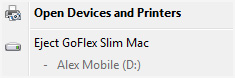
Figure 8-35 Remove/eject utility
When the PnP manager needs to reassign a device’s resources, it first asks the driver whether it can temporarily suspend further activity on the device by sending the driver a query-stop command. The driver either agrees to the request, if doing so wouldn’t cause data loss or corruption, or denies the request. As with a query-remove command, if the driver agrees to the request, the driver completes pending I/O operations and won’t initiate further I/O requests for the device that can’t be aborted and subsequently restarted. The driver typically queues new I/O requests so that the resource reshuffling is transparent to applications currently accessing the device. The PnP manager then sends the driver a stop command. At that point, the PnP manager can direct the driver to assign different resources to the device and once again send the driver a start-device command for the device.
The various Plug and Play commands essentially guide a device through an assortment of operational states, forming a well-defined state-transition table, which is shown in simplified form in Figure 8-36. (Several possible transitions and Plug and Play commands have been omitted for clarity. Also, the state diagram depicted is that implemented by function drivers. Bus drivers implement a more complex state diagram.) A state shown in the figure that we haven’t discussed is the one that results from the PnP manager’s surprise-remove command. This command results when either a user removes a device without warning, as when the user ejects a PCMCIA card without using the remove/eject utility, or the device fails. The surprise-remove command tells the driver to immediately cease all interaction with the device because the device is no longer attached to the system and to cancel any pending I/O requests.
)
Figure 8-36 Device Plug and Play state transitions
Driver Loading, Initialization, and Installation
Driver loading and initialization on Windows consists of two types of loading: explicit loading and enumeration-based loading. Explicit loading is guided by the HKLM\SYSTEM\CurrentControlSet\Services branch of the registry, as described in the section “Service Applications” in Chapter 4 in Part 1. Enumeration-based loading results when the PnP manager dynamically loads drivers for the devices that a bus driver reports during bus enumeration.
The Start Value
In Chapter 4 in Part 1, we explained that every driver and Windows service has a registry key under the Services branch of the current control set. The key includes values that specify the type of the image (for example, Windows service, driver, and file system), the path to the driver or service’s image file, and values that control the driver or service’s load ordering. There are two main differences between explicit device driver loading and Windows service loading:
Only device drivers can specify Start values of boot-start (0) or system-start (1).
Device drivers can use the Group and Tag values to control the order of loading within a phase of the boot, but unlike services, they can’t specify DependOnGroup or DependOnService values.
Chapter 13, describes the phases of the boot process and explains that a driver Start value of 0 means that the operating system loader loads the driver. A Start value of 1 means that the I/O manager loads the driver after the executive subsystems have finished initializing. The I/O manager calls driver initialization routines in the order that the drivers load within a boot phase. Like Windows services, drivers use the Group value in their registry key to specify which group they belong to; the registry value HKLM\SYSTEM\CurrentControlSet\Control\ServiceGroupOrder\List determines the order that groups are loaded within a boot phase.
A driver can further refine its load order by including a Tag value to control its order within a group. The I/O manager sorts the drivers within each group according to the Tag values defined in the drivers’ registry keys. Drivers without a tag go to the end of the list in their group. You might assume that the I/O manager initializes drivers with lower-number tags before it initializes drivers with higher-number tags, but such isn’t necessarily the case. The registry key HKLM\SYSTEM\CurrentControlSet\Control\GroupOrderList defines tag precedence within a group; with this key, Microsoft and device driver developers can take liberties with redefining the integer number system.
Here are the guidelines by which drivers set their Start value:
Non–Plug and Play drivers set their Start value to reflect the boot phase they want to load in.
Drivers, including both Plug and Play and non–Plug and Play drivers, that must be loaded by the boot loader during the system boot specify a Start value of boot-start (0). Examples include system bus drivers and the boot file system driver.
A driver that isn’t required for booting the system and that detects a device that a system bus driver can’t enumerate specifies a Start value of system-start (1). An example is the serial port driver, which informs the PnP manager of the presence of standard PC serial ports that were detected by Setup and recorded in the registry.
A non–Plug and Play driver or file system driver that doesn’t have to be present when the system boots specifies a Start value of auto-start (2). An example is the Multiple Universal Naming Convention (UNC) Provider (MUP) driver, which provides support for UNC-based path names to remote resources (for example, \\REMOTECOMPUTERNAME\SHARE).
Plug and Play drivers that aren’t required to boot the system specify a Start value of demand-start (3). Examples include network adapter drivers.
The only purpose that the Start values for Plug and Play drivers and drivers for enumerable devices have is to ensure that the operating system loader loads the driver—if the driver is required for the system to boot successfully. Beyond that, the PnP manager’s device enumeration process, described next, determines the load order for Plug and Play drivers.
Device Enumeration
The PnP manager begins device enumeration with a virtual bus driver called Root, which represents the entire computer system and acts as the bus driver for non–Plug and Play drivers and for the HAL. The HAL acts as a bus driver that enumerates devices directly attached to the motherboard as well as system components such as batteries. Instead of actually enumerating, the HAL relies on the hardware description the Setup process recorded in the registry to detect the primary bus (a PCI bus in most cases) and devices such as batteries and fans.
The primary bus driver enumerates the devices on its bus, possibly finding other buses, for which the PnP manager initializes drivers. Those drivers in turn can detect other devices, including other subsidiary buses. This recursive process of enumeration, driver loading (if the driver isn’t already loaded), and further enumeration proceeds until all the devices on the system have been detected and configured.
As the bus drivers report detected devices to the PnP manager, the PnP manager creates an internal tree called the device tree that represents the relationships between devices. Nodes in the tree are called devnodes, and a devnode contains information about the device objects that represent the device as well as other Plug and Play–related information stored in the devnode by the PnP manager. Figure 8-37 shows an example of a simplified device tree. This system is ACPI-compliant, so an ACPI-compliant HAL serves as the primary bus enumerator. A PCI bus serves as the system’s primary bus, which USB, ISA, and SCSI buses are connected to.
)
Figure 8-37 Example device tree
The Device Manager utility, which is accessible from the Computer Management snap-in in the Programs/Administrative Tools folder of the Start menu (and also from the Device Manager link of the System utility in Control Panel), shows a simple list of devices present on a system in its default configuration. You can also select the Devices By Connection option from the Device Manager’s View menu to see the devices as they relate to the device tree. Figure 8-38 shows an example of the Device Manager’s Devices By Connection view.
)
Figure 8-38 Device Manager showing the device tree
Taking device enumeration into account, the load and initialization order of drivers is as follows:
The I/O manager invokes the driver entry routine of each boot-start driver. If a boot driver has child devices, the I/O manager enumerates those devices, reporting their presence to the PnP manager. The child devices are configured and started if their drivers are boot-start drivers. If a device has a driver that isn’t a boot-start driver, the PnP manager creates a devnode for the device but doesn’t start it or load its driver.
After the boot-start drivers are initialized, the PnP manager walks the device tree, loading the drivers for devnodes that weren’t loaded in step 1 and starting their devices. As each device starts, the PnP manager enumerates related child devices, if a device has any, starting those devices’ drivers and performing enumeration of their children as required. The PnP manager loads the drivers for detected devices in this step regardless of the driver’s Start value. (The one exception is if the Start value is set to disabled.) At the end of this step, all Plug and Play devices have their drivers loaded and are started, except devices that aren’t enumerable and the children of those devices.
The PnP manager loads any drivers with a Start value of system-start that aren’t yet loaded. Those drivers detect and report their nonenumerable devices. The PnP manager loads drivers for those devices until all enumerated devices are configured and started.
The service control manager loads drivers marked as auto-start.
The device tree serves to guide both the PnP manager and the power manager as they issue Plug and Play and power IRPs to devices. In general, IRPs flow from the top of a devnode to the bottom, and in some cases a driver in one devnode creates new IRPs to send to other devnodes, always moving toward the root. The flow of Plug and Play and power IRPs is further described later in this chapter.
A record of all the devices detected since the system was installed is recorded under the HKLM\SYSTEM\CurrentControlSet\Enum registry key. Subkeys are in the form <Enumerator>\<Device ID>\<Instance ID>, where the enumerator is a bus driver, the device ID is a unique identifier for a type of device, and the instance ID uniquely identifies different instances of the same hardware.
Device Stacks
As the devnodes are created by the PnP manager, driver objects and device objects are created to manage and logically represent the linkage between the devnodes. This linkage is called a device stack, and it can be thought of as an ordered list of device object/driver pairs. Each device stack has a bottom and top, and Figure 8-39 shows that a device stack is made up of at least two, and sometimes more, device objects:
A physical device object (PDO) that the PnP manager instructs a bus driver to create when the bus driver reports the presence of a device on its bus during enumeration. The PDO represents the physical interface to the device and is always on the bottom of the device stack.
One or more optional filter device objects (FiDOs) that layer between the PDO and the functional device object (FDO; described later in this list) and that are created by bus filter drivers.
One or more optional FiDOs that layer between the PDO and the FDO (and that layer above any FiDOs created by bus filter drivers) that are created by lower-level filter drivers.
One (and only one) functional device object (FDO) that is created by the driver, which is called a function driver, that the PnP manager loads to manage a detected device. An FDO represents the logical interface to a device. A function driver can also act as a bus driver if devices are attached to the device represented by the FDO. The function driver often creates an interface (described earlier) to the FDO’s corresponding PDO so that applications and other drivers can open the device and interact with it. Sometimes function drivers are divided into a separate class/port driver and miniport driver that work together to manage I/O for the FDO.
One or more optional FiDOs that layer above the FDO and that are created by upper-level filter drivers.
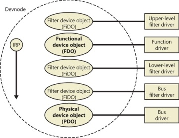
Figure 8-39 Device stack internals
)
)
Device stacks are built from the bottom up and rely on the I/O manager’s layering functionality, so IRPs flow from the top of a device stack toward the bottom. However, any level in the device stack can choose to complete an IRP. For example, the function driver can handle a read request without passing the IRP to the bus driver. Only when the function driver requires the help of a bus driver to perform bus-specific processing does the IRP flow all the way to the bottom and then into the device stack containing the bus driver.
Device Stack Driver Loading
So far, we’ve avoided answering two important questions: “How does the PnP manager determine what function driver to load for a particular device?” and “How do filter drivers register their presence so that they are loaded at appropriate times in the creation of a device stack?”
The answer to both these questions lies in the registry. When a bus driver performs device enumeration, it reports device identifiers for the devices it detects back to the PnP manager. The identifiers are bus-specific; for a USB bus, an identifier consists of a vendor ID (VID) for the hardware vendor that made the device and a product ID (PID) that the vendor assigned to the device. (See the WDK for more information on device ID formats.) Together these IDs form what Plug and Play calls a device ID. The PnP manager also queries the bus driver for an instance ID to help it distinguish different instances of the same hardware. The instance ID can describe either a bus-relative location (for example, the USB port) or a globally unique descriptor (for example, a serial number).
The device ID and instance ID are combined to form a device instance ID (DIID), which the PnP manager uses to locate the device’s key in the enumeration branch of the registry (HKLM\SYSTEM\CurrentControlSet\Enum). Figure 8-40 presents an example of a keyboard’s enumeration subkey. The device’s key contains descriptive data and includes values named Service and ClassGUID (which are obtained from a driver’s INF file) that help the PnP manager locate the device’s drivers.
)
Figure 8-40 Keyboard enumeration key
To deal with multifunction devices (such as all-in-one printers or cell phones with integrated camera and music player functionalities), Windows also supports a container ID property that can be associated with a devnode. The container ID is a globally unique identifier (GUID) that is unique to a single instance of a physical device and shared between all the function devnodes that belong to it, as shown in Figure 8-41.
)
Figure 8-41 All-in-one printer with a unique ID as seen by the PnP manager
The container ID is a property that, similar to the instance ID, is reported back by the bus driver of the corresponding hardware. Then, when the device is being enumerated, all devnodes associated with the same PDO share the container ID. Because Windows already supports many buses out of the box—such as PnP-X, Bluetooth, and USB—most device drivers can simply return the bus-specific ID, from which Windows will generate the corresponding container ID. For other kinds of devices or buses, the driver can generate its own unique ID through software.
Finally, when device drivers do not supply a container ID, Windows can make educated guesses by querying the topology for the bus, when that’s available, through mechanisms such as ACPI. By understanding whether a certain device is a child of another, and whether it is removable, hot-pluggable, or user-reachable (as opposed to an internal motherboard component), Windows is able to assign container IDs to device nodes that reflect multifunction devices correctly.
The final end-user benefit of grouping devices by container IDs is visible in the Devices And Printers UI present in modern versions of Windows. This feature is able to display the scanner, printer, and faxing components of an all-in-one printer as a single graphical element instead of as three distinct devices. For example, in Figure 8-42, the HP PSC 1500 series is identified as a single device.
)
Figure 8-42 Devices And Printers
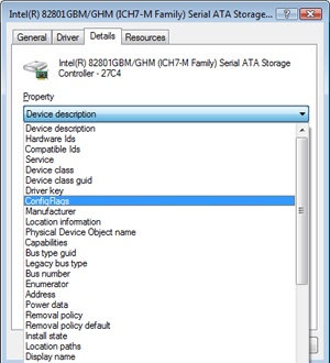
EXPERIMENT: Viewing Detailed Devnode Information in Device Manager
The Device Manager applet that you can access from the Hardware link of the System Control Panel application shows detailed information about a device node on its Details tab. The tab allows you to view an assortment of fields, including the devnode’s device instance ID, hardware ID, service name, filters, and power capabilities.
The following screen shows the selection combo box of the Details tab expanded to reveal the types of information you can access:
Using the ClassGUID value, the PnP manager locates the device’s class key under HKLM\SYSTEM\CurrentControlSet\Control\Class. The keyboard class key is shown in Figure 8-43. The enumeration key and class key supply the PnP manager with the information it needs to load the drivers necessary for the device’s devnode. Drivers are loaded in the following order:
Any lower-level filter drivers specified in the LowerFilters value of the device’s enumeration key.
Any lower-level filter drivers specified in the LowerFilters value of the device’s class key.
The function driver specified by the Service value in the device’s enumeration key. This value is interpreted as the driver’s key under HKLM\SYSTEM\CurrentControlSet\Services.
Any upper-level filter drivers specified in the UpperFilters value of the device’s enumeration key.
Any upper-level filter drivers specified in the UpperFilters value of the device’s class key.
)
Figure 8-43 Keyboard class key
In all cases, drivers are referenced by the name of their key under HKLM\SYSTEM\CurrentControlSet\Services.
The keyboard device shown in Figure 8-40 and Figure 8-43 has no lower-level filter drivers. The function driver is the i8042prt driver, and there are two upper-level filter drivers specified in the keyboard’s class key: kbdclass and vmkbd2.
Driver Installation
If the PnP manager encounters a device for which no driver is installed, it relies on the user-mode PnP manager to guide the installation process. If the device is detected during the system boot, a devnode is defined for the device, but the loading process is postponed until the user-mode PnP manager starts. (The user-mode PnP manager is implemented in %SystemRoot%\System32\Umpnpmgr.dll and runs in a service hosting process (Svchost.exe).)
The components involved in a driver’s installation are shown in Figure 8-44. Dark-shaded objects in the figure correspond to components generally supplied by the system, whereas lighter-shaded objects are those included in a driver’s installation files. First, a bus driver informs the PnP manager of a device it enumerates using a DIID (1). The PnP manager checks the registry for the presence of a corresponding function driver, and when it doesn’t find one, it informs the user-mode PnP manager (2) of the new device by its DIID. The user-mode PnP manager first tries to perform an automatic install without user intervention. If the installation process involves the posting of dialog boxes that require user interaction and the currently logged-on user has administrator privileges, (3) the user-mode PnP manager launches the Rundll32.exe application (the same application that hosts Control Panel utilities) to execute the Hardware Installation Wizard (%SystemRoot%\System32\Newdev.dll). If the currently logged-on user doesn’t have administrator privileges (or if no user is logged on) and the installation of the device requires user interaction, the user-mode PnP manager defers the installation until a privileged user logs on. The Hardware Installation Wizard uses Setupapi.dll and CfgMgr32.dll (configuration manager) API functions to locate INF files that correspond to drivers that are compatible with the detected device. This process might involve having the user insert installation media containing a vendor’s INF files, or the wizard might locate a suitable INF file in the driver store (%SystemRoot%\System32\DriverStore) that contains drivers that ship with Windows or others that are downloaded through Windows Update. Installation is performed in two steps. In the first, the third-party driver developer imports the driver package into the driver store, and in the second step, the system performs the actual installation, which is always done through the %SystemRoot%\System32\Drvinst.exe process.
)
Figure 8-44 Driver installation components
To find drivers for the new device, the installation process gets a list of hardware IDs and compatible IDs from the bus driver. These IDs describe all the various ways the hardware might be identified in a driver installation file (.inf). The lists are ordered so that the most specific description of the hardware is listed first. If matches are found in multiple INFs, more precise matches are preferred over less precise matches, digitally signed INFs are preferred over unsigned ones, and newer signed INFs are preferred over older signed ones. If a match is found based on a compatible ID, the Hardware Installation Wizard can choose to prompt for media in case a more up-to-date driver came with the hardware.
The INF file locates the function driver’s files and contains commands that fill in the driver’s enumeration and class keys, and the INF file might direct the Hardware Installation Wizard to (4) launch class or device coinstaller DLLs that perform class-specific or device-specific installation steps, such as displaying configuration dialog boxes that let the user specify settings for a device.
Before actually installing a driver, the user-mode PnP manager checks the system’s driver-signing policy. If the settings specify that the system should block or warn of the installation of unsigned drivers, the user-mode PnP manager checks the driver’s INF file for an entry that locates a catalog (a file that ends with the .cat extension) containing the driver’s digital signature.
Microsoft’s WHQL tests the drivers included with Windows and those submitted by hardware vendors. When a driver passes the WHQL tests, it is “signed” by Microsoft. This means that WHQL obtains a hash, or unique value representing the driver’s files, including its image file, and then cryptographically signs it with Microsoft’s private driver-signing key. The signed hash is stored in a catalog file and included on the Windows installation media or returned to the vendor that submitted the driver for inclusion with its driver.
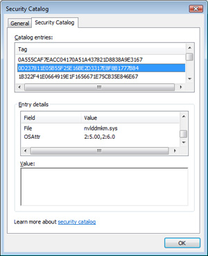
EXPERIMENT: Viewing Catalog Files
When you install a component such as a driver that includes a catalog file, Windows copies the catalog file to a directory under %SystemRoot%\System32\Catroot. Navigate to that directory in Explorer and you find the subdirectory that contains .cat files. Nt5.cat and Nt5ph.cat store the signatures and page hashes for Windows system files, for example.
If you open one of the catalog files, a dialog box appears with two pages. The page labeled General shows information about the signature on the catalog file, and the Security Catalog page has the hashes of the components that are signed with the catalog file. This screen shot of a catalog file for NVIDIA video drivers shows the hash for the video adapter’s kernel miniport driver. Other hashes in the catalog are associated with the various support DLLs that ship with the driver.
As it is installing a driver, the user-mode PnP manager extracts the driver’s signature from its catalog file, decrypts the signature using the public half of Microsoft’s driver-signing private/public key pair, and compares the resulting hash with a hash of the driver file it’s about to install. If the hashes match, the driver is verified as having passed WHQL testing. If a driver fails the signature verification, the user-mode PnP manager acts according to the settings of the system driver-signing policy, either failing the installation attempt, warning the user that the driver is unsigned, or silently installing the driver.
After a driver is installed, the kernel-mode PnP manager (step 5 in Figure 8-44) starts the driver and calls its add-device routine to inform the driver of the presence of the device it was loaded for. The construction of the device stack then continues as described earlier.