Understanding the Windows I/O System
- By Mark E. Russinovich, Kate Chase, Alex Ionescu
- 9/15/2012
I/O Processing
Now that we’ve covered the structure and types of drivers and the data structures that support them, let’s look at how I/O requests flow through the system. I/O requests pass through several predictable stages of processing. The stages vary depending on whether the request is destined for a device operated by a single-layered driver or for a device reached through a multilayered driver. Processing varies further depending on whether the caller specified synchronous or asynchronous I/O, so we’ll begin our discussion of I/O types with these two and then move on to others.
Types of I/O
Applications have several options for the I/O requests they issue. Furthermore, the I/O manager gives drivers the choice of implementing a shortcut I/O interface that can often mitigate IRP allocation for I/O processing. In this section, we’ll explain these options for I/O requests.
Synchronous and Asynchronous I/O
Most I/O operations that applications issue are synchronous (which is the default); that is, the application thread waits while the device performs the data operation and returns a status code when the I/O is complete. The program can then continue and access the transferred data immediately. When used in their simplest form, the Windows ReadFile and WriteFile functions are executed synchronously. They complete the I/O operation before returning control to the caller.
Asynchronous I/O allows an application to issue multiple I/O requests and continue executing while the device performs the I/O operation. This type of I/O can improve an application’s throughput because it allows the application thread to continue with other work while an I/O operation is in progress. To use asynchronous I/O, you must specify the FILE_FLAG_OVERLAPPED flag when you call the Windows CreateFile function. Of course, after issuing an asynchronous I/O operation, the thread must be careful not to access any data from the I/O operation until the device driver has finished the data operation. The thread must synchronize its execution with the completion of the I/O request by monitoring a handle of a synchronization object (whether that’s an event object, an I/O completion port, or the file object itself) that will be signaled when the I/O is complete.
Regardless of the type of I/O request, internally I/O operations issued to a driver on behalf of the application are performed asynchronously; that is, once an I/O request has been initiated, the device driver returns to the I/O system. Whether or not the I/O system returns immediately to the caller depends on whether the handle was opened for synchronous or asynchronous I/O. Figure 8-8 illustrates the flow of control when a read operation is initiated. Notice that if a wait is done, which depends on the overlapped flag in the file object, it is done in kernel mode by the NtReadFile function.
You can test the status of a pending asynchronous I/O operation with the Windows HasOverlappedIoCompleted macro. If you’re using I/O completion ports (described in the I/O Completion Ports section later in this chapter), you can use the GetQueuedCompletionStatus(Ex) function(s).
)
Figure 8-8 Control flow for an I/O operation
Fast I/O
Fast I/O is a special mechanism that allows the I/O system to bypass generating an IRP and instead go directly to the driver stack to complete an I/O request. (Fast I/O is described in detail in Chapters Chapter 11 and Chapter 12.) A driver registers its fast I/O entry points by entering them in a structure pointed to by the PFAST_IO_DISPATCH pointer in its driver object.
EXPERIMENT: Looking at a Driver’s Registered Fast I/O Routines
The !drvobj kernel debugger command can list the fast I/O routines that a driver registers in its driver object. However, typically only file system drivers have any use for fast I/O routines, although there are exceptions, such as network protocol drivers and bus filter drivers. The following output shows the fast I/O table for the NTFS file system driver object:
lkd> !drvobj \FileSystem\Ntfs 2 Driver object (fffffa8007d9fbe0) is for: \FileSystem\Ntfs DriverEntry: fffff880017d406c Ntfs!GsDriverEntry DriverStartIo: 00000000 DriverUnload: 00000000 AddDevice: 00000000 Dispatch routines: ... Fast I/O routines: FastIoCheckIfPossible fffff88001782230 Ntfs!NtfsFastIoCheck
IfPossible FastIoRead fffff880016efd60 Ntfs!NtfsCopyReadA FastIoWrite fffff880016f2a10 Ntfs!NtfsCopyWriteA FastIoQueryBasicInfo fffff880016e42e8 Ntfs!NtfsFastQueryBasic
The output shows that NTFS has registered its NtfsCopyReadA routine as the fast I/O table’s FastIoRead entry. As the name of this fast I/O entry implies, the I/O manager calls this function when issuing a read I/O request if the file is cached. If the call doesn’t succeed, the standard IRP path is selected.
Mapped File I/O and File Caching
Mapped file I/O is an important feature of the I/O system, one that the I/O system and the memory manager produce jointly. (See Chapter 10 for details on how mapped files are implemented.) Mapped file I/O refers to the ability to view a file residing on disk as part of a process’s virtual memory. A program can access the file as a large array without buffering data or performing disk I/O. The program accesses memory, and the memory manager uses its paging mechanism to load the correct page from the disk file. If the application writes to its virtual address space, the memory manager writes the changes back to the file as part of normal paging.
Mapped file I/O is available in user mode through the Windows CreateFileMapping and MapViewOfFile functions. Within the operating system, mapped file I/O is used for important operations such as file caching and image activation (loading and running executable programs). The other major consumer of mapped file I/O is the cache manager. File systems use the cache manager to map file data in virtual memory to provide better response time for I/O-bound programs. As the caller uses the file, the memory manager brings accessed pages into memory. Whereas most caching systems allocate a fixed number of bytes for caching files in memory, the Windows cache grows or shrinks depending on how much memory is available. This size variability is possible because the cache manager relies on the memory manager to automatically expand (or shrink) the size of the cache, using the normal working set mechanisms explained in Chapter 10, in this case applied to the system working set. By taking advantage of the memory manager’s paging system, the cache manager avoids duplicating the work that the memory manager already performs. (The workings of the cache manager are explained in detail in Chapter 11.)
Scatter/Gather I/O
Windows also supports a special kind of high-performance I/O that is called scatter/gather, available via the Windows ReadFileScatter and WriteFileGather functions. These functions allow an application to issue a single read or write from more than one buffer in virtual memory to a contiguous area of a file on disk instead of issuing a separate I/O request for each buffer. To use scatter/gather I/O, the file must be opened for noncached I/O, the user buffers being used have to be page-aligned, and the I/Os must be asynchronous (overlapped). Furthermore, if the I/O is directed at a mass storage device, the I/O must be aligned on a device sector boundary and have a length that is a multiple of the sector size.
I/O Request Packets
The I/O request packet (IRP) is where the I/O system stores information it needs to process an I/O request. When a thread calls an I/O API, the I/O manager constructs an IRP to represent the operation as it progresses through the I/O system. If possible, the I/O manager allocates IRPs from one of three per-processor IRP nonpaged look-aside lists: the small-IRP look-aside list stores IRPs with one stack location (IRP stack locations are described shortly), the medium-IRP look-aside list contains IRPs with 4 stack locations (which can also be used for IRPs that require only 2 or 3 stack locations), and the large-IRP look-aside list contains IRPs with more than 4 stack locations—by default, the system stores IRPs with 10 stack locations on the large-IRP look-aside list, but once per minute the system adjusts the number of stack locations allocated and can increase it up to a maximum of 20, based on how many stack locations have been recently required. Additionally, these lists are backed by global look-aside lists as well, allowing efficient cross-CPU IRP flow. If an IRP requires more stack locations than are contained in the IRPs on the large-IRP look-aside list, the I/O manager allocates IRPs from nonpaged pool. After allocating and initializing an IRP, the I/O manager stores a pointer to the caller’s file object in the IRP.
Figure 8-9 shows a sample I/O request that demonstrates the relationship between an IRP and the file, device, and driver objects described in the preceding sections. Although this example shows an I/O request to a single-layered device driver, most I/O operations aren’t this direct; they involve one or more layered drivers. (This case will be shown later in this section.)
)
Figure 8-9 Data structures involved in a single-layered driver I/O request
IRP Stack Locations
An IRP consists of two parts: a fixed header (often referred to as the IRP’s body) and one or more stack locations. The fixed portion contains information such as the type and size of the request, whether the request is synchronous or asynchronous, a pointer to a buffer for buffered I/O, and state information that changes as the request progresses. An IRP stack location contains a function code (consisting of a major code and a minor code), function-specific parameters, and a pointer to the caller’s file object. The major function code identifies which of a driver’s dispatch routines the I/O manager invokes when passing an IRP to a driver. An optional minor function code sometimes serves as a modifier of the major function code. Power and Plug and Play commands always have minor function codes.
Most drivers specify dispatch routines to handle only a subset of possible major function codes, including create (open), read, write, device I/O control, power, Plug and Play, system control (for WMI commands), cleanup, and close. (See the following experiment for a complete listing of major function codes.) File system drivers are an example of a driver type that often fills in most or all of its dispatch entry points with functions. In contrast, a driver for a simple USB device would probably fill in only the routines needed for open, close, read, write, and sending I/O control codes. The I/O manager sets any dispatch entry points that a driver doesn’t fill to point to its own IopInvalidDeviceRequest, which completes the IRP with an error status indicating that the major function specified in the IRP is invalid for that device.
EXPERIMENT: Looking at Driver Dispatch Routines
You can obtain a listing of the functions a driver has defined for its dispatch routines by entering a 7 after the driver object’s name (or address) in the !drvobj kernel debugger command. The following output shows that drivers support 28 IRP types.
lkd> !drvobj \Driver\kbdclass 7 Driver object (fffffa800adc2e70) is for: \Driver\kbdclass Driver Extension List: (id , addr) Device Object list: fffffa800b04fce0 fffffa800abde560 DriverEntry: fffff880071c8ecc kbdclass!GsDriverEntry DriverStartIo: 00000000 DriverUnload: 00000000 AddDevice: fffff880071c53b4 kbdclass!KeyboardAddDevice Dispatch routines: [00] IRP_MJ_CREATE fffff880071bedd4 kbdclass!
While active, each IRP is usually queued in an IRP list associated with the thread that requested the I/O. (Otherwise, it is stored in the file object when performing thread-agnostic I/O, which is described earlier in this chapter.) This allows the I/O system to find and cancel any outstanding IRPs if a thread terminates with I/O requests that have not been completed. Additionally, paging I/O IRPs are also associated with the faulting thread (although they are not cancellable). This allows Windows to use the thread-agnostic I/O optimization —when an APC is not used to complete I/O if the current thread is the initiating thread. This means that page faults occur inline, instead of requiring APC delivery.
EXPERIMENT: Looking at a Thread’s Outstanding IRPs
When you use the !thread command, it prints any IRPs associated with the thread. Run the kernel debugger with live debugging, and locate the service control manager process (Services.exe) in the output generated by the !process command:
lkd> !process 0 0 **** NT ACTIVE PROCESS DUMP **** ... PROCESS 8623b840 SessionId: 0 Cid: 0270 Peb: 7ffd6000
Then dump the threads for the process by executing the !process command on the process object. You should see many threads, with most of them having IRPs reported in the IRP List area of the thread information (note that the debugger will show only the first 17 IRPs for a thread that has more than 17 outstanding I/O requests):
lkd> !process 8623b840 PROCESS 8623b840 SessionId: 0 Cid: 0270 Peb: 7ffd6000
Choose an IRP, and examine it with the !irp command:
lkd> !irp 86a81190
Irp is active with 1 stacks 1 is current (= 0x86a81200)
 No Mdl: No System Buffer: Thread 86a1d248:  Irp stack trace.
     cmd  flg cl Device   File     Completion-Context
>[  3, 0]   0  1 86156328 86a4e7a0 00000000-00000000    pending
           \FileSystem\Npfs
            Args: 00000800 00000000 00000000 00000000
This IRP has a major function of 3, which corresponds to IRP_MJ_READ, which can be found in WDM.h. It has one stack location and is targeted at a device owned by the Npfs driver (the Named Pipe File System driver). (Npfs is described in Chapter 7, “Networking,” in Part 1.)
IRP Buffer Management
When an application or a device driver indirectly creates an IRP by using the NtReadFile, NtWriteFile, or NtDeviceIoControlFile system services (or the Windows API functions corresponding to these services, which are ReadFile, WriteFile, and DeviceIoControl), the I/O manager determines whether it needs to participate in the management of the caller’s input or output buffers. The I/O manager performs three types of buffer management:
Buffered I/O The I/O manager allocates a buffer in nonpaged pool of equal size to the caller’s buffer. For write operations, the I/O manager copies the caller’s buffer data into the allocated buffer when creating the IRP. For read operations, the I/O manager copies data from the allocated buffer to the user’s buffer when the IRP completes and then frees the allocated buffer. The nonpaged pool buffer is pointed to by the IRP’s AssociatedIrp.SystemBuffer field.
Direct I/O When the I/O manager creates the IRP, it locks the user’s buffer into memory (that is, makes it nonpaged). When the I/O manager has finished using the IRP, it unlocks the buffer. The I/O manager stores a description of the memory in the form of a memory descriptor list (MDL). An MDL specifies the physical memory occupied by a buffer. (See the WDK for more information on MDLs.) Devices that perform direct memory access (DMA) require only physical descriptions of buffers, so an MDL is sufficient for the operation of such devices. (Devices that support DMA transfer data directly between the device and the computer’s memory by using a DMA controller, not the CPU.) If a driver must access the contents of a buffer, however, it can map the buffer into the system’s address space.
Neither I/O The I/O manager doesn’t perform any buffer management. Instead, buffer management is left to the discretion of the device driver, which can choose to manually perform the steps the I/O manager performs with the other buffer management types.
For each type of buffer management, the I/O manager places applicable references in the IRP to the locations of the input and output buffers. The type of buffer management the I/O manager performs depends on the type of buffer management a driver requests for each type of operation. A driver registers the type of buffer management it desires for read and write operations in the device object that represents the device. Device I/O control operations (those requested by calling NtDeviceIoControlFile) are specified with driver-defined I/O control codes, and a control code contains bits specifying the buffer management the I/O manager should use when issuing IRPs that contain that code.
Drivers commonly use buffered I/O when callers transfer requests smaller than one page (4 KB on x86 processors) or when the device does not support DMA. They use direct I/O for larger requests on DMA-aware devices. File system drivers commonly use neither I/O because no buffer management overhead is incurred when data can be copied from the file system cache into the caller’s original buffer. The reason that most drivers don’t use neither I/O is that a pointer to a caller’s buffer is valid only while a thread of the caller’s process is executing.
Drivers that use neither I/O to access buffers that might be located in user space must take special care to ensure that buffer addresses are both valid and do not reference kernel-mode memory. Scalar values, however, are perfectly safe to pass, although a few drivers have only a scalar value to pass around. Failure to do so could result in crashes or in security vulnerabilities, where applications have access to kernel-mode memory or can inject code into the kernel. The ProbeForRead and ProbeForWrite functions that the kernel makes available to drivers verify that a buffer resides entirely in the user-mode portion of the address space. To avoid a crash from referencing an invalid user-mode address, drivers can access user-mode buffers from within exception-handling code (called try/except blocks in C) that catch any invalid memory faults and translate them into error codes to return to the application. Additionally, drivers should also capture all input data into a kernel buffer instead of relying on user-mode addresses, since the caller could always modify the data behind the driver’s back, even if the memory address itself is still valid.
I/O Request to a Single-Layered Driver
This section traces a synchronous I/O request to a single-layered kernel-mode device driver. In its most simplified form, handling a synchronous I/O to a single-layered driver consists of seven steps:
The I/O request passes through a subsystem DLL.
The subsystem DLL calls the I/O manager’s NtWriteFile service.
The I/O manager allocates an IRP describing the request and sends it to the driver (a device driver in this case) by calling its own IoCallDriver function.
The driver transfers the data in the IRP to the device and starts the I/O operation.
The device signals I/O completion by interrupting the CPU.
The device driver services the interrupt.
The driver calls the I/O manager’s IoCompleteRequest function to inform it that it has finished processing the IRP’s request, and the I/O manager completes the I/O request.
These seven steps are illustrated in Figure 8-10.
)
Figure 8-10 Issuing and completing a synchronous I/O request
Now that we’ve seen how an I/O is initiated, let’s take a closer look at interrupt processing and I/O completion.
Servicing an Interrupt
After an I/O device completes a data transfer, it interrupts for service, and the Windows kernel, I/O manager, and device driver are called into action. Figure 8-11 illustrates the first phase of the process. (Chapter 3 in Part 1 describes the interrupt dispatching mechanism, including DPCs. We’ve included a brief recap here because DPCs are key to I/O processing on interrupt-driven devices.)
)
Figure 8-11 Servicing a device interrupt (phase 1)
When a device interrupt occurs, the processor transfers control to the kernel trap handler, which indexes into its interrupt dispatch table to locate the ISR for the device. ISRs in Windows typically handle device interrupts in two steps. When an ISR is first invoked, it usually remains at device IRQL only long enough to capture the device status and then stop the device’s interrupt. It then queues a DPC and exits, dismissing the interrupt. Later, when the DPC routine is called at IRQL 2, the device finishes processing the interrupt. When that’s done, the device calls the I/O manager to complete the I/O and dispose of the IRP. It will also start the next I/O request that is waiting in the device queue.
The advantage of using a DPC to perform most of the device servicing is that any blocked interrupt whose IRQL lies between the device IRQL and the DPC/dispatch IRQL (2) is allowed to occur before the lower-priority DPC processing occurs. Intermediate-level interrupts are thus serviced more promptly than they otherwise would be, and this reduces latency on the system. This second phase of an I/O (the DPC processing) is illustrated in Figure 8-12.
)
Figure 8-12 Servicing a device interrupt (phase 2)
Completing an I/O Request
After a device driver’s DPC routine has executed, some work still remains before the I/O request can be considered finished. This third stage of I/O processing is called I/O completion and is initiated when a driver calls IoCompleteRequest to inform the I/O manager that it has completed processing the request specified in the IRP (and the stack location that it owns). The steps I/O completion entails vary with different I/O operations. For example, all the I/O drivers record the outcome of the operation in an I/O status block, a data structure stored in the IRP and then copied back into a caller-supplied buffer during I/O completion. Similarly, some drivers that perform buffered I/O require the I/O system to return data to the calling thread.
In both cases, the I/O system must copy data that is stored in system memory into the caller’s virtual address space. If the IRP completed synchronously, the caller’s address space is current and directly accessible, but if the IRP completed asynchronously, the I/O manager must delay IRP completion until it can access the caller’s address space. To gain access to the caller’s virtual address space, the I/O manager must transfer the data “in the context of the caller’s thread”—that is, while the caller’s thread is executing (which implies that the caller’s process is the current process and its address space is mapped on the processor). It does so by queuing a special kernel-mode asynchronous procedure call (APC) to the thread. This process is illustrated in Figure 8-13.
)
Figure 8-13 Completing an I/O request (phase 1)
As explained in Chapter 3 in Part 1, APCs execute in the context of a particular thread, whereas a DPC executes in arbitrary thread context, meaning that the DPC routine can’t touch the user-mode process address space. Remember too that DPCs have a higher IRQL than APCs.
The next time that the thread begins to execute at low IRQL (below DISPATCH_LEVEL), the pending APC is delivered. The kernel transfers control to the I/O manager’s APC routine, which copies the data (for a read request) and the return status into the original caller’s address space, frees the IRP representing the I/O operation, and either sets the caller’s file handle (and any caller-supplied event) to the signaled state for synchronous I/O or queues an entry to the caller’s I/O completion port. The I/O is now considered complete. The original caller or any other threads that are waiting on the file (or other object) handle are released from their waiting state and readied for execution. Figure 8-14 illustrates the second stage of I/O completion.
)
Figure 8-14 Completing an I/O request (phase 2)
Although this is the normal path through which I/O completion occurs, Windows can take a shortcut if the I/O happens to be completed in the same thread that issued the I/O request. In this situation, as long as APC delivery was not disabled (in order to maintain compatibility with legacy versions of Windows, which always used an APC, even in this situation), the phase 2 I/O completion mechanism is called inline.
A final note about I/O completion: the asynchronous I/O functions ReadFileEx and WriteFileEx allow a caller to supply a user-mode APC as a parameter. If the caller does so, the I/O manager queues this APC to the caller’s thread APC queue as the last step of I/O completion. This feature allows a caller to specify a subroutine to be called when an I/O request is completed or canceled. User-mode APC completion routines execute in the context of the requesting thread and are delivered only when the thread enters an alertable wait state (such as calling the Windows SleepEx, WaitForSingleObjectEx, or WaitForMultipleObjectsEx function).
Synchronization
Drivers must synchronize their access to global driver data and hardware registers for two reasons:
The execution of a driver can be preempted by higher-priority threads and time-slice (or quantum) expiration or can be interrupted by higher IRQL interrupts.
On multiprocessor systems, Windows can run driver code simultaneously on more than one processor.
Without synchronization, corruption could occur—for example, because device driver code running at passive IRQL (0) when a caller initiates an I/O operation can be interrupted by a device interrupt, causing the device driver’s ISR to execute while its own device driver is already running. If the device driver was modifying data that its ISR also modifies, such as device registers, heap storage, or static data, the data can become corrupted when the ISR executes. Figure 8-15 illustrates this problem.
)
Figure 8-15 Concurrent access to shared data by a device driver dispatch routine and ISR
To avoid this situation, a device driver written for Windows must synchronize its access to any data that can be accessed at more than one IRQL. Before attempting to update shared data, the device driver must lock out all other threads (or CPUs, in the case of a multiprocessor system) to prevent them from updating the same data structure.
The Windows kernel provides a special synchronization routine called KeSynchronizeExecution that device drivers call when they access data that their ISRs also access. This kernel synchronization routine keeps the ISR from executing while the shared data is being accessed. A driver can also use KeAcquireInterruptSpinLock to access an interrupt object’s spinlock directly, although drivers can generally behave better by relying on KeSynchronizeExecution for synchronization with an ISR because calling this function at PASSIVE_LEVEL will synchronize with a KEVENT in the interrupt object structure instead of raising IRQL.
By now, you should realize that although ISRs require special attention, any data that a device driver uses is subject to being accessed by the same device driver running on another processor. Therefore, it’s critical for device driver code to synchronize its use of any global or shared data (or any accesses to the physical device itself). If the ISR uses that data, the device driver must use KeSynchronizeExecution or KeAcquireInterruptSpinLock; otherwise, the device driver can use standard kernel spinlocks (which are acquired at DISPATCH_LEVEL (IRQL 2).
I/O Requests to Layered Drivers
The preceding section showed how an I/O request to a simple device controlled by a single device driver is handled. I/O processing for file-based devices or for requests to other layered drivers happens in much the same way. The major difference is, obviously, that one or more additional layers of processing are added to the model.
Figure 8-16 shows a very simplified, illustrative example of how an asynchronous I/O request might travel through layered drivers. It uses as an example a disk controlled by a file system.
)
Figure 8-16 Queuing an asynchronous request to layered drivers
Once again, the I/O manager receives the request and creates an I/O request packet to represent it. This time, however, it delivers the packet to a file system driver. The file system driver exercises great control over the I/O operation at that point. Depending on the type of request the caller made, the file system can send the same IRP to the disk driver or it can generate additional IRPs and send them separately to the disk driver.
The file system is most likely to reuse an IRP if the request it receives translates into a single straightforward request to a device. For example, if an application issues a read request for the first 512 bytes in a file stored on a volume, the NTFS file system would simply call the volume manager driver, asking it to read one sector from the volume, beginning at the file’s starting location.
To accommodate its reuse by multiple drivers in a request to layered drivers, an IRP contains a series of IRP stack locations (not to be confused with the CPU stack used by threads to store function parameters and return addresses). These data areas, one for every driver that will be called, contain the information that each driver needs to execute its part of the request—for example, function code, parameters, and driver context information. As Figure 8-16 illustrates, additional stack locations are filled in as the IRP passes from one driver to the next. You can think of an IRP as being similar to a stack in the way data is added to it and removed from it during its lifetime. However, an IRP isn’t associated with any particular process, and its allocated size doesn’t grow or shrink. The I/O manager allocates an IRP from one of its IRP look-aside lists or nonpaged system memory at the beginning of the I/O operation.
EXPERIMENT: Examining IRPs
In this experiment, you’ll find an uncompleted IRP on the system, and you’ll determine the IRP type, the device at which it’s directed, the driver that manages the device, the thread that issued the IRP, and what process the thread belongs to.
At any point in time, there are at least a few uncompleted IRPs on a system. This occurs because there are many devices to which applications can issue IRPs that a driver will complete only when a particular event occurs, such as data becoming available. One example is a blocking read from a network endpoint. You can see the outstanding IRPs on a system with the !irpfind kernel debugger command:
lkd> !irpfind Scanning large pool allocation table for Tag: Irp? (86c16000 : 86d16000) Searching NonPaged pool (80000000 : ffc00000) for Tag: Irp? Irp [ Thread ] irpStack: (Mj,Mn) DevObj [Driver]
The entry in bold in the output describes an IRP that is directed at the Kbdclass driver, so it is likely that the IRP was issued by the Windows subsystem raw input thread that reads keyboard input. Examining the IRP with the !irp command reveals the following:
lkd> !irp 862dee28
Irp is active with 3 stacks 3 is current (= 0x862deee0)
 No Mdl: System buffer=864f5108: Thread 864fc030:  Irp stack trace.
     cmd  flg cl Device   File     Completion-Context
 [  0, 0]   0  0 00000000 00000000 00000000-00000000

            Args: 00000000 00000000 00000000 00000000
 [  0, 0]   0  0 00000000 00000000 00000000-00000000

            Args: 00000000 00000000 00000000 00000000
>[  3, 0]   0  1 84baf030 864f52f8 00000000-00000000    pending
           \Driver\kbdclass
            Args: 00000078 00000000 00000000 00000000
The active stack location is at the bottom. (The debugger shows the active location with a “>” character in column one.) It has a major function of 3, which corresponds to IRP_MJ_READ.
The next step is to see what device object the IRP is targeting by executing the !devobj command on the device object address in the active stack location.
lkd> !devobj 84baf030
Device object (84baf030) is for:
 KeyboardClass1 \Driver\kbdclass DriverObject 84b706b8
Current Irp 00000000 RefCount 0 Type 0000000b Flags 00002044
Dacl 8b0538b8 DevExt 84baf0e8 DevObjExt 84baf1c8
ExtensionFlags (0x00000800)
                             Unknown flags 0x00000800
AttachedTo (Lower) 84badaa0 \Driver\TermDD
Device queue is not busy.
The device at which the IRP is targeted is KeyboardClass1. The presence of a device object owned by the Termdd driver attached beneath it reveals that it is the device that represents keyboard input from a Terminal Server client, not the physical keyboard.
We can see details about the thread and process that issued the IRP by using the !thread and !process commands:
lkd> !thread 864fc030
THREAD 864fc030  Cid 01d4.0234  Teb: 7ffd9000 Win32Thread: ffac4008
              WAIT: (WrUserRequest) KernelMode Alertable
    8623c620  SynchronizationEvent
    864fc3a8  NotificationTimer
    864fc378  SynchronizationTimer
    864fc360  SynchronizationEvent
IRP List:
    86af0e28: (0006,01d8) Flags: 00060970  Mdl: 00000000
    86503958: (0006,0268) Flags: 00060970  Mdl: 00000000
    862dee28: (0006,01d8) Flags: 00060970  Mdl: 00000000
Not impersonating
DeviceMap                 8b0087d8
Owning Process            0       Image:         <Unknown>
Attached Process          864d2d90       Image:         csrss.exe
Wait Start TickCount      171909         Ticks: 29 (0:00:00:00.452)
Context Switch Count      121222
UserTime                  00:00:00.000
KernelTime                00:00:00.717
Win32 Start Address 0x764d9a30
Stack Init 96f46000 Current 96f45c28 Base 96f46000 Limit 96f43000 Call 0
Priority 15 BasePriority 13 PriorityDecrement 0 IoPriority 2
 PagePriority 5

lkd> !process 864d2d90
PROCESS 864d2d90  SessionId: 1  Cid: 0208    Peb: 7ffdf000
  ParentCid: 0200
    DirBase: ce21e0a0  ObjectTable: 964a6e68  HandleCount: 284.
    Image: csrss.exe
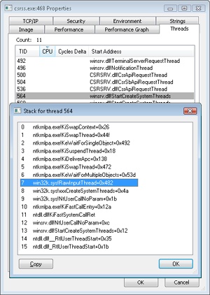
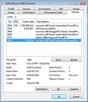
Locating the thread in Process Explorer by opening the Properties dialog box for Csrss.exe and going to the Threads tab confirms, through the names of the functions on its stack, the role of the thread as a raw input thread for the Windows subsystem:
After the disk controller’s DMA adapter finishes a data transfer, the disk controller interrupts the host, causing the ISR for the disk controller to run, which requests a DPC callback completing the IRP, as shown in Figure 8-17.
As an alternative to reusing a single IRP, a file system can establish a group of associated IRPs that work in parallel on a single I/O request. For example, if the data to be read from a file is dispersed across the disk, the file system driver might create several IRPs, each of which reads some portion of the request from a different sector. This queuing is illustrated in Figure 8-18.
)
Figure 8-17 Completing a layered I/O request
)
Figure 8-18 Queuing associated IRPs
The file system driver delivers the associated IRPs to the volume manager, which in turn sends them to the disk device driver, which queues them to the disk device. They are processed one at a time, and the file system driver keeps track of the returned data. When all the associated IRPs complete, the I/O system completes the original IRP and returns to the caller, as shown in Figure 8-19.
)
Figure 8-19 Completing associated IRPs
Thread Agnostic I/O
In the I/O models described thus far, IRPs are queued to the thread that initiated the I/O and are completed by the I/O manager issuing an APC to that thread so that process-specific and thread-specific context is accessible by completion processing. Thread-specific I/O processing is usually sufficient for the performance and scalability needs of most applications, but Windows also includes support for thread agnostic I/O via two mechanisms:
I/O completion ports, which are described at length later in this chapter
Locking the user buffer into memory and mapping it into the system address space
With I/O completion ports, the application decides when it wants to check for the completion of I/O, so the thread that happens to have issued an I/O request is not necessarily relevant because any other thread can perform the completion request. As such, instead of completing the IRP inside the specific thread’s context, it can be completed in the context of any thread that has access to the completion port.
Likewise, with a locked and kernel-mapped version of the user buffer, there’s no need to be in the same memory address space as the issuing thread because the kernel can access the memory from arbitrary contexts. Applications can enable this mechanism by using SetFileIoOverlappedRange as long as they have the SE_LOCK_MEMORY privilege.
With both completion port I/O and I/O on file buffers set by SetFileIoOverlappedRange, the I/O manager associates the IRPs with the file object to which they have been issued instead of with the issuing thread. The !fileobj extension in WinDbg will show an IRP list for file objects that are used with these mechanisms.
In the next sections, we’ll see how thread agnostic I/O increases the reliability and performance of applications on Windows.
I/O Cancellation
While there are many ways in which IRP processing occurs and various methods to complete an I/O request, a great many I/O processing operations actually end in cancellation rather than completion. For example, a device may require removal while IRPs are still active, or the user might cancel a long-running operation to a device—for example, a network operation. Another situation requiring I/O cancellation support is thread and process termination. When a thread exits, the I/Os associated with the thread must be cancelled because the I/O operations are no longer relevant, and the thread cannot be deleted until the outstanding I/Os have completed.
The Windows I/O manager, working with drivers, must deal with these requests efficiently and reliably to provide a smooth user experience. Drivers manage this need by registering a cancel routine for their cancellable I/O operations (typically, those operations that are still enqueued and not yet in progress), which is invoked by the I/O manager to cancel an I/O operation. When drivers fail to play their role in these scenarios, users may experience unkillable processes, which have disappeared visually but linger and still appear in Task Manager or Process Explorer. (See Chapter 5, “Processes, Threads, and Jobs” in Part 1 for more information on processes and threads.)
User-Initiated I/O Cancellation
Most software uses one thread to handle user interface (UI) input and one or more threads to perform work, including I/O. In some cases, when a user wants to abort an operation that was initiated in the UI, an application might need to cancel outstanding I/O operations. Operations that complete quickly might not require cancellation, but for operations that take arbitrary amounts of time—like large data transfers or network operations—Windows provides support for cancelling both synchronous operations and asynchronous operations. A thread can cancel its own outstanding asynchronous I/Os by calling CancelIo. It can cancel all asynchronous I/Os issued to a specific file handle, regardless of by which thread, in the same process with CancelIoEx. CancelIoEx also works on operations associated with I/O completion ports through the thread-agnostic support in Windows that was mentioned earlier because the I/O system keeps track of a completion port’s outstanding I/Os by linking them with the completion port.
For cancelling synchronous I/Os, a thread can call CancelSynchronousIo. CancelSynchronousIo enables even create (open) operations to be cancelled when supported by a device driver, and several drivers in Windows support this functionality, including the drivers that manage network file systems (for example, MUP, DFS, and SMB), which can cancel open operations to network paths. Figures Figure 8-20 and Figure 8-21 show synchronous and asynchronous I/O cancellation. (To a driver, all cancel processing looks the same.)
)
Figure 8-20 Synchronous I/O cancellation
)
Figure 8-21 Asynchronous I/O cancellation
I/O Cancellation for Thread Termination
The other scenario in which I/Os must be cancelled is when a thread exits, either directly or as the result of its process terminating (which causes the threads of the process to terminate). Because every thread has a list of IRPs associated with it, the I/O manager can walk this list, look for cancellable IRPs, and cancel them. Unlike CancelIoEx, which does not wait for an IRP to be cancelled before returning, the process manager will not allow thread termination to proceed until all I/Os have been cancelled. As a result, if a driver fails to cancel an IRP, the process and thread object will remain allocated until the system shuts down. Figure 8-22 illustrates the process termination scenario.
)
Figure 8-22 Cancellation during process termination
EXPERIMENT: Debugging an Unkillable Process
In this experiment, we’ll use Notmyfault from Sysinternals (we’ll cover Notmyfault heavily in the “Crash Dump Analysis” section in Chapter 14) to force the unkillable process problem to exhibit itself by causing the Myfault.sys driver (which Notmyfault.exe uses) to indefinitely hold an IRP without having registered a cancel routine for it.
To start, run Notmyfault.exe, select Hang With IRP from the list of options on the Hang tab, and then click the Hang button. The dialog box should look like the following when properly configured.
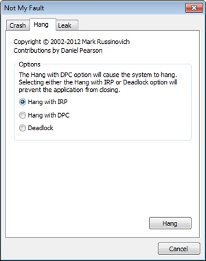
You shouldn’t see anything happen, and you should be able to click the Cancel button to quit the application. However, you should still see the Notmyfault process in Task Manager or Process Explorer. Attempts to terminate the process will fail because Windows will wait forever for the IRP to complete given that the Myfault driver doesn’t register a cancel routine.
To debug an issue such as this, you can use WinDbg to look at what the thread is currently doing. Open a local kernel debugger session, and start by listing the information about the Notmyfault.exe process with the !process command:
lkd> !process 0 7 notmyfault.exe PROCESS 86843ab0 SessionId: 1 Cid: 0594 Peb: 7ffd8000
From the stack trace, you can see that the thread that initiated the I/O realized that the IRP had been cancelled (IopSynchronousServiceTail called IopCancelAlertedRequest) and is now waiting for the cancellation or completion. The next step is to use the same debugger extension command used in the previous experiments, !irp, and attempt to analyze the problem. Copy the IRP pointer, and examine it with !irp:
lkd> !irp 86a51228
Irp is active with 1 stacks 1 is current (= 0x86a51298)
 No Mdl: No System Buffer: Thread 868139b8:  Irp stack trace.
     cmd  flg cl Device   File     Completion-Context
>[  e, 0]   5  0 86727920 86797c08 00000000-00000000
           \Driver\MYFAULT
            Args: 00000000 00000000 83360020 00000000
From this output, it is obvious who the culprit driver is: \Driver\MYFAULT, or Myfault.sys. The name of the driver emphasizes that the only way this situation can happen is through a driver problem and not a buggy application. Unfortunately, now that you know which driver caused this issue, there isn’t much you can do—a system reboot is necessary because Windows can never safely assume it is okay to ignore the fact that cancellation hasn’t occurred yet. The IRP could return at any time and cause corruption of system memory. If you encounter this situation in practice, you should check for a newer version of the driver, which might include a fix for the bug.
I/O Completion Ports
Writing a high-performance server application requires implementing an efficient threading model. Having either too few or too many server threads to process client requests can lead to performance problems. For example, if a server creates a single thread to handle all requests, clients can become starved because the server will be tied up processing one request at a time. A single thread could simultaneously process multiple requests, switching from one to another as I/O operations are started, but this architecture introduces significant complexity and can’t take advantage of systems with more than one logical processor. At the other extreme, a server could create a big pool of threads so that virtually every client request is processed by a dedicated thread. This scenario usually leads to thread-thrashing, in which lots of threads wake up, perform some CPU processing, block while waiting for I/O, and then, after request processing is completed, block again waiting for a new request. If nothing else, having too many threads results in excessive context switching, caused by the scheduler having to divide processor time among multiple active threads.
The goal of a server is to incur as few context switches as possible by having its threads avoid unnecessary blocking, while at the same time maximizing parallelism by using multiple threads. The ideal is for there to be a thread actively servicing a client request on every processor and for those threads not to block when they complete a request if additional requests are waiting. For this optimal process to work correctly, however, the application must have a way to activate another thread when a thread processing a client request blocks on I/O (such as when it reads from a file as part of the processing).
The IoCompletion Object
Applications use the IoCompletion executive object, which is exported to the Windows API as a completion port, as the focal point for the completion of I/O associated with multiple file handles. Once a file is associated with a completion port, any asynchronous I/O operations that complete on the file result in a completion packet being queued to the completion port. A thread can wait for any outstanding I/Os to complete on multiple files simply by waiting for a completion packet to be queued to the completion port. The Windows API provides similar functionality with the WaitForMultipleObjects API function, but the advantage that completion ports have is that concurrency, or the number of threads that an application has actively servicing client requests, is controlled with the aid of the system.
When an application creates a completion port, it specifies a concurrency value. This value indicates the maximum number of threads associated with the port that should be running at any given time. As stated earlier, the ideal is to have one thread active at any given time for every processor in the system. Windows uses the concurrency value associated with a port to control how many threads an application has active. If the number of active threads associated with a port equals the concurrency value, a thread that is waiting on the completion port won’t be allowed to run. Instead, it is expected that one of the active threads will finish processing its current request and check to see whether another packet is waiting at the port. If one is, the thread simply grabs the packet and goes off to process it. When this happens, there is no context switch, and the CPUs are utilized nearly to their full capacity.
Using Completion Ports
Figure 8-23 shows a high-level illustration of completion port operation. A completion port is created with a call to the Windows API function CreateIoCompletionPort. Threads that block on a completion port become associated with the port and are awakened in last in, first out (LIFO) order so that the thread that blocked most recently is the one that is given the next packet. Threads that block for long periods of time can have their stacks swapped out to disk, so if there are more threads associated with a port than there is work to process, the in-memory footprints of threads blocked the longest are minimized.
A server application will usually receive client requests via network endpoints that are identified by file handles. Examples include Windows Sockets 2 (Winsock2) sockets or named pipes. As the server creates its communications endpoints, it associates them with a completion port and its threads wait for incoming requests by calling GetQueuedCompletionStatus on the port. When a thread is given a packet from the completion port, it will go off and start processing the request, becoming an active thread. A thread will block many times during its processing, such as when it needs to read or write data to a file on disk or when it synchronizes with other threads. Windows detects this activity and recognizes that the completion port has one less active thread. Therefore, when a thread becomes inactive because it blocks, a thread waiting on the completion port will be awakened if there is a packet in the queue.
)
Figure 8-23 I/O completion port operation
Microsoft’s guidelines are to set the concurrency value roughly equal to the number of processors in a system. Keep in mind that it’s possible for the number of active threads for a completion port to exceed the concurrency limit. Consider a case in which the limit is specified as 1. A client request comes in, and a thread is dispatched to process the request, becoming active. A second request arrives, but a second thread waiting on the port isn’t allowed to proceed because the concurrency limit has been reached. Then the first thread blocks waiting for a file I/O, so it becomes inactive. The second thread is then released, and while it’s still active, the first thread’s file I/O is completed, making it active again. At that point—and until one of the threads blocks—the concurrency value is 2, which is higher than the limit of 1. Most of the time, the count of active threads will remain at or just above the concurrency limit.
The completion port API also makes it possible for a server application to queue privately defined completion packets to a completion port by using the PostQueuedCompletionStatus function. A server typically uses this function to inform its threads of external events, such as the need to shut down gracefully.
Applications can use thread agnostic I/O, described earlier, with I/O completion ports to avoid associating threads with their own I/Os and associating them with a completion port object instead. In addition to the other scalability benefits of I/O completion ports, their use can minimize context switches. Standard I/O completions must be executed by the thread that initiated the I/O, but when an I/O associated with an I/O completion port completes, the I/O manager uses any waiting thread to perform the completion operation.
I/O Completion Port Operation
Windows applications create completion ports by calling the Windows API CreateIoCompletionPort and specifying a NULL completion port handle. This results in the execution of the NtCreateIoCompletion system service. The executive’s IoCompletion object contains a kernel synchronization object called a kernel queue. Thus, the system service creates a completion port object and initializes a queue object in the port’s allocated memory. (A pointer to the port also points to the queue object because the queue is at the start of the port memory.) A kernel queue object has a concurrency value that is specified when a thread initializes it, and in this case the value that is used is the one that was passed to CreateIoCompletionPort. KeInitializeQueue is the function that NtCreateIoCompletion calls to initialize a port’s queue object.
When an application calls CreateIoCompletionPort to associate a file handle with a port, the NtSetInformationFile system service is executed with the file handle as the primary parameter. The information class that is set is FileCompletionInformation, and the completion port’s handle and the CompletionKey parameter from CreateIoCompletionPort are the data values. NtSetInformationFile dereferences the file handle to obtain the file object and allocates a completion context data structure.
Finally, NtSetInformationFile sets the CompletionContext field in the file object to point at the context structure. When an asynchronous I/O operation completes on a file object, the I/O manager checks to see whether the CompletionContext field in the file object is non-NULL. If it is, the I/O manager allocates a completion packet and queues it to the completion port by calling KeInsertQueue with the port as the queue on which to insert the packet. (Remember that the completion port object and queue object have the same address.)
When a server thread invokes GetQueuedCompletionStatus, the system service NtRemoveIoCompletion is executed. After validating parameters and translating the completion port handle to a pointer to the port, NtRemoveIoCompletion calls IoRemoveIoCompletion, which eventually calls KeRemoveQueueEx. For high-performance scenarios, it’s possible that multiple I/Os may have been completed, and although the thread will not block, it will still call into the kernel each time to get one item. The GetQueuedCompletionStatus or GetQueuedCompletionStatusEx API allows applications to retrieve more than one I/O completion status at the same time, reducing the number of user-to-kernel roundtrips and maintaining peak efficiency. Internally, this is implemented through the NtRemoveIoCompletionEx function, which calls IoRemoveIoCompletion with a count of queued items, which is passed on to KeRemoveQueueEx.
As you can see, KeRemoveQueueEx and KeInsertQueue are the engines behind completion ports. They are the functions that determine whether a thread waiting for an I/O completion packet should be activated. Internally, a queue object maintains a count of the current number of active threads and the maximum number of active threads. If the current number equals or exceeds the maximum when a thread calls KeRemoveQueueEx, the thread will be put (in LIFO order) onto a list of threads waiting for a turn to process a completion packet. The list of threads hangs off the queue object. A thread’s control block data structure (KTHREAD) has a pointer in it that references the queue object of a queue that it’s associated with; if the pointer is NULL, the thread isn’t associated with a queue.
Windows keeps track of threads that become inactive because they block on something other than the completion port by relying on the queue pointer in a thread’s control block. The scheduler routines that possibly result in a thread blocking (such as KeWaitForSingleObject, KeDelayExecution-Thread, and so on) check the thread’s queue pointer. If the pointer isn’t NULL, the functions call KiActivateWaiterQueue, a queue-related function that decrements the count of active threads associated with the queue. If the resultant number is less than the maximum and at least one completion packet is in the queue, the thread at the front of the queue’s thread list is awakened and given the oldest packet. Conversely, whenever a thread that is associated with a queue wakes up after blocking, the scheduler executes the function KiUnwaitThread, which increments the queue’s active count.
Finally, the PostQueuedCompletionStatus Windows API function results in the execution of the NtSetIoCompletion system service. This function simply inserts the specified packet onto the completion port’s queue by using KeInsertQueue.
Figure 8-24 shows an example of a completion port object in operation. Even though two threads are ready to process completion packets, the concurrency value of 1 allows only one thread associated with the completion port to be active, and so the two threads are blocked on the completion port.
)
Figure 8-24 I/O completion port operation
Finally, the exact notification model of the I/O completion port can be fine-tuned through the SetFileCompletionNotificationModes API, which allows application developers to take advantage of additional, specific improvements that usually require code changes but can offer even more throughput. Three notification-mode optimizations are supported, which are listed in Table 8-3. Note that these modes are per file handle and permanent.
Table 8-3 I/O Completion Port Notification Modes
Notification Mode |
Meaning |
Skip completion port on success |
If the following three conditions are true, the I/O manager does not queue a completion entry to the port when it would ordinarily do so. First, a completion port must be associated with the file handle; second, the file must be opened for asynchronous I/O; third, the request must return success immediately without returning ERROR_PENDING. |
Skip set event on handle |
The I/O manager does not set the event for the file object if a request returns with a success code or the error returned is ERROR_PENDING and the function that is called is not a synchronous function. If an explicit event is provided for the request, it is still signaled. |
Skip set user event on fast I/O |
The I/O manager does not set the explicit event provided for the request if a request takes the fast I/O path and returns with a success code or the error returned is ERROR_PENDING and the function that is called is not a synchronous function. |
I/O Prioritization
Without I/O priority, background activities like search indexing, virus scanning, and disk defragmenting can severely impact the responsiveness of foreground operations. A user launching an application or opening a document while another process is performing disk I/O, for example, experiences delays as the foreground task waits for disk access. The same interference also affects the streaming playback of multimedia content like music from a disk.
Windows includes two types of I/O prioritization to help foreground I/O operations get preference: priority on individual I/O operations and I/O bandwidth reservations.
I/O Priorities
The Windows I/O manager internally includes support for five I/O priorities, as shown in Table 8-4, but only three of the priorities are used. (Future versions of Windows may support High and Low.)
Table 8-4 I/O Priorities
I/O Priority |
Usage |
Critical |
Memory manager |
High |
Not used |
Normal |
Normal application I/O |
Low |
Not used |
Very Low |
Scheduled tasks, Superfetch, defragmenting, content indexing, background activities |
I/O has a default priority of Normal, and the memory manager uses Critical when it wants to write dirty memory data out to disk under low-memory situations to make room in RAM for other data and code. The Windows Task Scheduler sets the I/O priority for tasks that have the default task priority to Very Low. The priority specified by applications that perform background processing is Very Low. All of the Windows background operations, including Windows Defender scanning and desktop search indexing, use Very Low I/O priority.
Prioritization Strategies
Internally, these five I/O priorities are divided into two I/O prioritization modes, called strategies. These are the hierarchy prioritization and the idle prioritization strategies. Hierarchy prioritization deals with all the I/O priorities except Very Low. It implements the following strategy:
All critical-priority I/O must be processed before any high-priority I/O.
All high-priority I/O must be processed before any normal-priority I/O.
All normal-priority I/O must be processed before any low-priority I/O.
All low-priority I/O is processed after any higher-priority I/O.
As each application generates I/Os, IRPs are put on different I/O queues based on their priority, and the hierarchy strategy decides the ordering of the operations.
The idle prioritization strategy, on the other hand, uses a separate queue for non-idle priority I/O. Because the system processes all hierarchy prioritized I/O before idle I/O, it’s possible for the I/Os in this queue to be starved, as long as there’s even a single non-idle I/O on the system in the hierarchy priority strategy queue.
To avoid this situation, as well as to control backoff (the sending rate of I/O transfers), the idle strategy uses a timer to monitor the queue and guarantee that at least one I/O is processed per unit of time (typically, half a second). Data written using non-idle I/O priority also causes the cache manager to write modifications to disk immediately instead of doing it later and to bypass its read-ahead logic for read operations that would otherwise preemptively read from the file being accessed. The prioritization strategy also waits for 50 milliseconds after the completion of the last non-idle I/O in order to issue the next idle I/O. Otherwise, idle I/Os would occur in the middle of non-idle streams, causing costly seeks.
Combining these strategies into a virtual global I/O queue for demonstration purposes, a snapshot of this queue might look similar to Figure 8-25. Note that within each queue, the ordering is first-in, first-out (FIFO). The order in the figure is shown only as an example.
)
Figure 8-25 Sample entries in a global I/O queue
User-mode applications can set I/O priority on three different objects. SetPriorityClass and SetThreadPriority set the priority for all the I/Os that either the entire process or specific threads will generate (the priority is stored in the IRP of each request). SetFileInformationByHandle can set the priority for a specific file object (the priority is stored in the file object). Drivers can also set I/O priority directly on an IRP by using the IoSetIoPriorityHint API.
The two prioritization strategies are implemented by two different types of drivers. The hierarchy strategy is implemented by the storage port drivers, which are responsible for all I/Os on a specific port, such as ATA, SCSI, or USB. Only the ATA port driver (%SystemRoot%\System32\Ataport.sys) and USB port driver (%SystemRoot%\System32\Usbstor.sys) implement this strategy, while the SCSI and storage port drivers (%SystemRoot%\System32\Scsiport.sys and %SystemRoot%\System32\Stor port.sys) do not.
This means that consumer mass storage devices such as IDE or SATA hard drives and USB flash disks will take advantage of I/O prioritization, while devices based on SCSI, Fibre Channel, and iSCSI will not.
On the other hand, it is the system storage class device driver (%SystemRoot%\System32\Class pnp.sys) that enforces the idle strategy, so it automatically applies to I/Os directed at all storage devices, including SCSI drives. This separation ensures that idle I/Os will be subject to back-off algorithms to ensure a reliable system during operation under high idle I/O usage and so that applications that use them can make forward progress. Placing support for this strategy in the Microsoft-provided class driver avoids performance problems that would have been caused by lack of support for it in legacy third-party port drivers.
Figure 8-26 displays a simplified view of the storage stack and where each strategy is implemented. See Chapter 9 for more information on the storage stack.
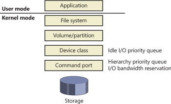
Figure 8-26 Implementation of I/O prioritization across the storage stack
I/O Priority Inversion Avoidance (I/O Priority Inheritance)
To avoid I/O priority inversion (in which a high-I/O-priority thread can be starved by a low-I/O-priority thread), the executive resource (ERESOURCE) locking functionality utilizes several strategies. The ERESOURCE was picked for the implementation of I/O priority inheritance particularly because of its heavy use in file system and storage drivers, where most I/O priority inversion issues can appear.
If an ERESOURCE is being acquired by a thread with low I/O priority, and there are currently waiters on the ERESOURCE with normal or higher priority, the current thread is temporarily boosted to normal I/O priority by using the PsBoostThreadIo API, which increments the IoBoostCount in the ETHREAD structure.
It then calls the IoBoostThreadIoPriority API, which enumerates all the IRPs queued to the target thread (recall that each thread has a list of pending IRPs) and checks which ones have a lower priority than the target priority (normal in this case), thus identifying pending idle I/O priority IRPs. In turn, the device object responsible for each of those IRPs is identified, and the I/O manager checks whether a priority callback has been registered, which driver developers can do through the IoRegisterPriorityCallback API and by setting the DO_PRIORITY_CALLBACK_ENABLED flag on their device object. Depending on whether the IRP was a paging I/O, this mechanism is called the threaded boost or the paging boost.
Finally, if no matching IRPs were found, but the thread has at least some pending IRPs, all are boosted regardless of device object or priority, which is called blanket boosting.
I/O Priority Boosts and Bumps
A few other subtle modifications to normal I/O paths are used by Windows to avoid starvation, inversion, or otherwise unwanted scenarios when I/O priority is being used. Typically, these modifications are done by boosting I/O priority when needed. The following scenarios exhibit this behavior.
When a driver is being called with an IRP targeted to a particular file object, Windows makes sure that if the request comes from kernel mode, the IRP uses normal priority even if the file object has a lower I/O priority hint. This is called the kernel bump.
When reads or writes to the paging file are occurring (through IoPageRead and IoPageWrite), Windows checks whether the request comes from kernel mode and is not being performed on behalf of Superfetch (which always uses idle I/O). In this case, the IRP uses normal priority even if the current thread has a lower I/O priority. This is called the paging bump.
The following experiment will show you an example of Very Low I/O priority and how you can use Process Monitor to look at I/O priorities on different requests.
EXPERIMENT: Very Low vs. Normal I/O Throughput
You can use the IO Priority sample application (included in the book’s utilities) to look at the throughput difference between two threads with different I/O priorities. Launch IoPriority.exe, make sure Thread 1 is checked to use Low priority, and then click the Start IO button. You should notice a significant difference in speed between the two threads, as shown in the following screen.
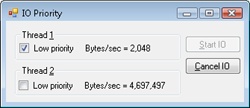
You should also notice that Thread 1’s throughput remains fairly constant, around 2 KB/s. This can easily be explained by the fact that IO Priority performs its I/Os at 2 KB/s, which means that the idle prioritization strategy is kicking in and guaranteeing at least one I/O each half-second. Otherwise, Thread 2 would starve any I/O that Thread 1 is attempting to make.
Note that if both threads run at low priority and the system is relatively idle, their throughput will be roughly equal to the throughput of a single normal I/O priority in the example. This is because low priority I/Os are not artificially throttled or otherwise hindered if there isn’t any competition from higher priority I/O.
You can also use Process Monitor to trace IO Priority’s I/Os and look at their I/O priority hint. Launch Process Monitor, configure a filter for IoPriority.exe, and repeat the experiment. In this application, Thread 1 writes to File_1, and Thread 2 writes to File_2. Scroll down until you see a write to File_1, and you should see output similar to that shown next.
)
)
You can see that I/Os directed at File_1 have a priority of Very Low. By looking at the Time Of Day column, you’ll also notice that the I/Os are spaced 0.5 second from each other—another sign of the idle strategy in action.
Finally, by using Process Explorer, you can identify Thread 1 in the IoPriority process by looking at the I/O priority for each of its threads on the Threads tab of its process Properties dialog box. You can also see that the priority for the thread is lower than the default of 8 (normal), which indicates that the thread is probably running in background priority mode. The following screen shot shows what you should expect to see.
Note that if IO Priority sets the priority on File_1 instead of on the issuing thread, both threads would look the same. Only Process Monitor could show you the difference in I/O priorities.
Bandwidth Reservation (Scheduled File I/O)
Windows I/O bandwidth reservation support is useful for applications that desire consistent I/O throughput. Using the SetFileBandwidthReservation call, a media player application asks the I/O system to guarantee it the ability to read data from a device at a specified rate. If the device can deliver data at the requested rate and existing reservations allow it, the I/O system gives the application guidance as to how fast it should issue I/Os and how large the I/Os should be.
The I/O system won’t service other I/Os unless it can satisfy the requirements of applications that have made reservations on the target storage device. Figure 8-27 shows a conceptual timeline of I/Os issued on the same file. The shaded regions are the only ones that will be available to other applications. If I/O bandwidth is already taken, new I/Os will have to wait until the next cycle.
)
Figure 8-27 Effect of I/O requests during bandwidth reservation
Like the hierarchy prioritization strategy, bandwidth reservation is implemented at the port driver level, which means it is available only for IDE, SATA, or USB-based mass-storage devices.
Container Notifications
Container notifications are specific classes of events that drivers can register for through an asynchronous callback mechanism by using the IoRegisterContainerNotification API and selecting the notification class that interests them. Thus far, one class is implemented in Windows, which is the IoSessionStateNotification class. This class allows drivers to have their registered callback invoked whenever a change in the state of a given session is registered. The following changes are supported:
A session is created or terminated
A user connects to or disconnects from a session
A user logs on to or logs off from a session
By specifying a device object that belongs to a specific session, the driver callback will be active only for that session, while by specifying a global device object (or no device object at all), the driver will receive notifications for all events on a system. This feature is particularly useful for devices that participate in the Plug and Play device redirection functionality that is provided through Terminal Services, which allows a remote device to be visible on the connecting host’s Plug and Play manager bus as well (such as audio or printer device redirection). Once the user disconnects from a session with audio playback, for example, the device driver needs a notification in order to stop redirecting the source audio stream.
Driver Verifier
Driver Verifier is a mechanism that can be used to help find and isolate common bugs in device drivers or other kernel-mode system code. Microsoft uses Driver Verifier to check its own device drivers as well as all device drivers that vendors submit for Windows Hardware Quality Labs (WHQL) testing. Doing so ensures that the drivers submitted are compatible with Windows and free from common driver errors. (Although not described in this book, there is also a corresponding Application Verifier tool that has resulted in quality improvements for user-mode code in Windows.)
Also, although Driver Verifier serves primarily as a tool to help device driver developers discover bugs in their code, it is also a powerful tool for system administrators experiencing crashes. Chapter 14 describes its role in crash analysis troubleshooting.
Driver Verifier consists of support in several system components: the memory manager, I/O manager, and HAL all have driver verification options that can be enabled. These options are configured using the Driver Verifier Manager (%SystemRoot%\System32\Verifier.exe). When you run Driver Verifier with no command-line arguments, it presents a wizard-style interface, as shown in Figure 8-28.
)
Figure 8-28 Driver Verifier Manager
You can also enable and disable Driver Verifier, as well as display current settings, by using its command-line interface. From a command prompt, type verifier /? to see the switches.
Even when you don’t select any options, Driver Verifier monitors drivers selected for verification, looking for a number of illegal and boundary operations, including calling kernel-memory pool functions at invalid IRQL, double-freeing memory, allocating synchronization objects from NonPagedPoolSession memory, referencing a freed object, delaying shutdown for longer than 20 minutes, and requesting a zero-size memory allocation.
What follows is a description of the I/O-related verification options (shown in Figure 8-29). The options related to memory management are described in Chapter 10, along with how the memory manager redirects a driver’s operating system calls to special verifier versions.
)
Figure 8-29 Driver Verifier I/O-related options
These options have the following effects:
I/O Verification When this option is selected, the I/O manager allocates IRPs for verified drivers from a special pool and their usage is tracked. In addition, the Verifier crashes the system when an IRP is completed that contains an invalid status or when an invalid device object is passed to the I/O manager. This option also monitors all IRPs to ensure that drivers mark them correctly when completing them asynchronously, that they manage device-stack locations correctly, and that they delete device objects only once. In addition, the Verifier randomly stresses drivers by sending them fake power management and WMI IRPs, changing the order in which devices are enumerated, and adjusting the status of PnP and power IRPs when they complete to test for drivers that return incorrect status from their dispatch routines. Finally, Verifier also detects incorrect re-initialization of remove locks while they are still being held due to pending device removal.
DMA Checking DMA (direct access memory) is a hardware-supported mechanism that allows devices to transfer data to or from physical memory without involving the CPU. The I/O manager provides a number of functions that drivers use to initiate and control DMA operations, and this option enables checks for correct use of the functions and buffers that the I/O manager supplies for DMA operations.
Force Pending I/O Requests For many devices, asynchronous I/Os complete immediately, so drivers may not be coded to properly handle the occasional asynchronous I/O. When this option is enabled, the I/O manager will randomly return STATUS_PENDING in response to a driver’s calls to IoCallDriver, which simulates the asynchronous completion of an I/O.
IRP Logging This option monitors a driver’s use of IRPs and makes a record of IRP usage, which is stored as WMI information. You can then use the Dc2wmiparser.exe utility in the WDK to convert these WMI records to a text file. Note that only 20 IRPs for each device will be recorded—each subsequent IRP will overwrite the entry added least recently. After a reboot, this information is discarded, so Dc2wmiparser.exe should be run if the contents of the trace are to be analyzed later.