Understanding the Windows I/O System
- By Mark E. Russinovich, Kate Chase, Alex Ionescu
- 9/15/2012
Device Drivers
To integrate with the I/O manager and other I/O system components, a device driver must conform to implementation guidelines specific to the type of device it manages and the role it plays in managing the device. In this section, we’ll look at the types of device drivers Windows supports as well as the internal structure of a device driver.
Types of Device Drivers
Windows supports a wide range of device driver types and programming environments. Even within a type of device driver, programming environments can differ, depending on the specific type of device for which a driver is intended. The broadest classification of a driver is whether it is a user-mode or kernel-mode driver. Windows supports a couple of types of user-mode drivers:
Windows subsystem printer drivers translate device-independent graphics requests to printer-specific commands. These commands are then typically forwarded to a kernel-mode port driver such as the universal serial bus (USB) printer port driver (Usbprint.sys).
User-Mode Driver Framework (UMDF) drivers are hardware device drivers that run in user mode. They communicate to the kernel-mode UMDF support library through ALPC. See the User-Mode Driver Framework (UMDF) section later in this chapter for more information.
In this chapter, the focus is on kernel-mode device drivers. There are many types of kernel-mode drivers, which can be divided into the following basic categories:
File system drivers accept I/O requests to files and satisfy the requests by issuing their own, more explicit, requests to mass storage or network device drivers.
Plug and Play drivers work with hardware and integrate with the Windows power manager and PnP manager. They include drivers for mass storage devices, video adapters, input devices, and network adapters.
Non–Plug and Play drivers, which also include kernel extensions, are drivers or modules that extend the functionality of the system. They do not typically integrate with the PnP or power managers because they typically do not manage an actual piece of hardware. Examples include network API and protocol drivers. Process Monitor’s driver, described in Chapter 4 in Part 1, is also an example.
Within the category of kernel-mode drivers are further classifications based on the driver model that the driver adheres to and its role in servicing device requests.
WDM Drivers
WDM drivers are device drivers that adhere to the Windows Driver Model (WDM). WDM includes support for Windows power management, Plug and Play, and WMI, and most Plug and Play drivers adhere to WDM. There are three types of WDM drivers:
Bus drivers manage a logical or physical bus. Examples of buses include PCMCIA, PCI, USB, and IEEE 1394. A bus driver is responsible for detecting and informing the PnP manager of devices attached to the bus it controls as well as managing the power setting of the bus.
Function drivers manage a particular type of device. Bus drivers present devices to function drivers via the PnP manager. The function driver is the driver that exports the operational interface of the device to the operating system. In general, it’s the driver with the most knowledge about the operation of the device.
Filter drivers logically layer either above or below function drivers (these are called function filters) or above the bus driver (these are called bus filters), augmenting or changing the behavior of a device or another driver. For example, a keyboard capture utility could be implemented with a keyboard filter driver that layers above the keyboard function driver.
In WDM, no one driver is responsible for controlling all aspects of a particular device. The bus driver is responsible for detecting bus membership changes (device addition or removal), assisting the PnP manager in enumerating the devices on the bus, accessing bus-specific configuration registers, and, in some cases, controlling power to devices on the bus. The function driver is generally the only driver that accesses the device’s hardware.
Layered Drivers
Support for an individual piece of hardware is often divided among several drivers, each providing a part of the functionality required to make the device work properly. In addition to WDM bus drivers, function drivers, and filter drivers, hardware support might be split between the following components:
Class drivers implement the I/O processing for a particular class of devices, such as disk, keyboard, or CD-ROM, where the hardware interfaces have been standardized, so one driver can serve devices from a wide variety of manufacturers.
Miniclass drivers implement I/O processing that is vendor-defined for a particular class of devices. For example, although there is a standardized battery class driver written by Microsoft, both uninterruptible power supplies (UPS) and laptop batteries have highly specific interfaces that differ wildly between manufacturers, such that a miniclass is required from the vendor. Miniclass drivers are essentially kernel-mode DLLs and do not do IRP processing directly—the class driver calls into them, and they import functions from the class driver.
Port drivers implement the processing of an I/O request specific to a type of I/O port, such as SATA, and are implemented as kernel-mode libraries of functions rather than actual device drivers. Port drivers are almost always written by Microsoft because the interfaces are typically standardized in such a way that different vendors can still share the same port driver. However, in certain cases, third parties may need to write their own for specialized hardware. In some cases, the concept of “I/O port” extends to cover logical ports as well. For example, NDIS is the network “port” driver, and Dxgport/Videoprt are the DirectX/video “port” drivers.
Miniport drivers map a generic I/O request to a type of port into an adapter type, such as a specific network adapter. Miniport drivers are actual device drivers that import the functions supplied by a port driver. Miniport drivers are written by third parties, and they provide the interface for the port driver. Like miniclass drivers, they are kernel-mode DLLs and do not do IRP processing directly.
A simplified example for illustrative purposes will help demonstrate how device drivers work at a high level. A file system driver accepts a request to write data to a certain location within a particular file. It translates the request into a request to write a certain number of bytes to the disk at a particular (that is, the logical) location. It then passes this request (via the I/O manager) to a simple disk driver. The disk driver, in turn, translates the request into a physical location on the disk and communicates with the disk to write the data. This layering is illustrated in Figure 8-3.
)
Figure 8-3 Layering of a file system driver and a disk driver
This figure illustrates the division of labor between two layered drivers. The I/O manager receives a write request that is relative to the beginning of a particular file. The I/O manager passes the request to the file system driver, which translates the write operation from a file-relative operation to a starting location (a sector boundary on the disk) and a number of bytes to write. The file system driver calls the I/O manager to pass the request to the disk driver, which translates the request to a physical disk location and transfers the data.
Because all drivers—both device drivers and file system drivers—present the same framework to the operating system, another driver can easily be inserted into the hierarchy without altering the existing drivers or the I/O system. For example, several disks can be made to seem like a very large single disk by adding a driver. This logical, volume manager driver is located between the file system and the disk drivers, as shown in the conceptual, simplified architectural diagram presented in Figure 8-4. (For the actual storage driver stack diagram, see Figure 9-3 in Chapter 9). Volume manager drivers are described in more detail in Chapter 9.
)
Figure 8-4 Adding a layered driver
EXPERIMENT: Viewing the Loaded Driver List
You can see a list of registered drivers by executing the Msinfo32.exe utility from the Run dialog box of the Start menu. Select the System Drivers entry under Software Environment to see the list of drivers configured on the system. Those that are loaded have the text “Yes” in the Started column, as shown here:
)
You can also view the list of loaded kernel-mode drivers with Process Explorer from Windows Sysinternals (http://www.microsoft.com/technet/sysinternals). Run Process Explorer, select the System process, and select DLLs from the Lower Pane View menu entry in the View menu:
)
Process Explorer lists the loaded drivers, their names, version information (including company and description), and load address (assuming you have configured Process Explorer to display the corresponding columns).
Finally, if you’re looking at a crash dump (or live system) with the kernel debugger, you can get a similar display with the kernel debugger lm kv command:
lkd> lm kv start end module name 82007000 823c0000 nt (pdb symbols) c:\programming\symbols\ntkrpamp.pdb\37D328E3BAE5460F8E662756ED80951D2\ntkrpamp.pdb Loaded symbol image file: ntkrpamp.exe Image path: ntkrpamp.exe Image name: ntkrpamp.exe Timestamp: Fri Jan 18 21:30:58 2008 (47918B12) CheckSum: 00372038 ImageSize: 003B9000 File version: 6.0.6001.18000 Product version: 6.0.6001.18000 File flags: 0 (Mask 3F) File OS: 40004 NT Win32 File type: 1.0 App File date: 00000000.00000000 Translations: 0409.04b0 CompanyName: Microsoft Corporation ProductName: Microsoft® Windows® Operating System InternalName: ntkrpamp.exe OriginalFilename: ntkrpamp.exe ProductVersion: 6.0.6001.18000 FileVersion: 6.0.6001.18000 (longhorn_rtm.080118-1840) FileDescription: NT Kernel & System LegalCopyright: © Microsoft Corporation. All rights reserved. 823c0000 823f3000 hal (deferred) Image path: halmacpi.dll Image name: halmacpi.dll Timestamp: Fri Jan 18 21:27:20 2008 (47918A38) CheckSum: 0003859F ImageSize: 00033000 Translations: 0000.04b0 0000.04e0 0409.04b0 0409.04e0 82600000 82671000 ksecdd (deferred) Image path: \SystemRoot\System32\Drivers\ksecdd.sys Image name: ksecdd.sys Timestamp: Fri Jan 18 21:41:20 2008 (47918D80) CheckSum: 0006E742 ImageSize: 00071000 Translations: 0000.04b0 0000.04e0 0409.04b0 0409.04e0
Structure of a Driver
The I/O system drives the execution of device drivers. Device drivers consist of a set of routines that are called to process the various stages of an I/O request. Figure 8-5 illustrates the key driver-function routines.
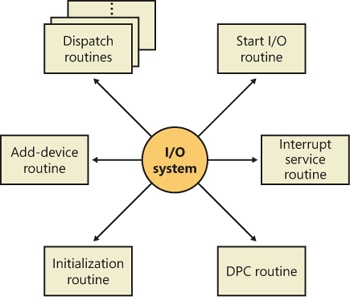
Figure 8-5 Primary device driver routines
An initialization routine The I/O manager executes a driver’s initialization routine, which is set by the WDK to GSDriverEntry, when it loads the driver into the operating system. GSDriverEntry initializes the compiler’s protection against stack-overflow errors (called a cookie) and then calls DriverEntry, which is what the driver writer must implement. The routine fills in system data structures to register the rest of the driver’s routines with the I/O manager and performs any global driver initialization that’s necessary.
An add-device routine A driver that supports Plug and Play implements an add-device routine. The PnP manager sends a notification to the driver via this routine whenever a device for which the driver is responsible is detected. In this routine, a driver typically creates a device object (described later in this chapter) to represent the device.
A set of dispatch routines Dispatch routines are the main entry points that a device driver provides. Some examples are open, close, read, and write and any other capabilities the device, file system, or network supports. When called on to perform an I/O operation, the I/O manager generates an IRP and calls a driver through one of the driver’s dispatch routines.
A start I/O routine A driver can use a start I/O routine to initiate a data transfer to or from a device. This routine is defined only in drivers that rely on the I/O manager to queue their incoming I/O requests. The I/O manager serializes IRPs for a driver by ensuring that the driver processes only one IRP at a time. Drivers can process multiple IRPs concurrently, but serialization is usually required for most devices because they cannot concurrently handle multiple I/O requests.
An interrupt service routine (ISR) When a device interrupts, the kernel’s interrupt dispatcher transfers control to this routine. In the Windows I/O model, ISRs run at device interrupt request level (DIRQL), so they perform as little work as possible to avoid blocking lower IRQL interrupts. (See Chapter 3, “System Mechanisms,” in Part 1 for more information on IRQLs.) An ISR usually queues a deferred procedure call (DPC), which runs at a lower IRQL (DPC/dispatch level), to execute the remainder of interrupt processing. (Only drivers for interrupt-driven devices have ISRs; a file system driver, for example, doesn’t have one.)
An interrupt-servicing DPC routine A DPC routine performs most of the work involved in handling a device interrupt after the ISR executes. The DPC routine executes at a lower IRQL (DPC/dispatch level) than that of the ISR, which runs at device level, to avoid blocking other interrupts. A DPC routine initiates I/O completion and starts the next queued I/O operation on a device.
Although the following routines aren’t shown in Figure 8-5, they’re found in many types of device drivers:
One or more I/O completion routines A layered driver might have I/O completion routines that will notify it when a lower-level driver finishes processing an IRP. For example, the I/O manager calls a file system driver’s I/O completion routine after a device driver finishes transferring data to or from a file. The completion routine notifies the file system driver about the operation’s success, failure, or cancellation, and it allows the file system driver to perform cleanup operations.
A cancel I/O routine If an I/O operation can be canceled, a driver can define one or more cancel I/O routines. When the driver receives an IRP for an I/O request that can be canceled, it assigns a cancel routine to the IRP, and as the IRP goes through various stages of processing, this routine can change, or outright disappear, if the current operation is not cancellable. If a thread that issues an I/O request exits before the request is completed or cancels the operation (with the CancelIo Windows function, for example), the I/O manager executes the IRP’s cancel routine if one is assigned to it. A cancel routine is responsible for performing whatever steps are necessary to release any resources acquired during the processing that has already taken place for the IRP as well as for completing the IRP with a canceled status.
Fast dispatch routines Drivers that make use of the cache manager in Windows (see Chapter 11, for more information on the cache manager), such as file system drivers, typically provide these routines to allow the kernel to bypass typical I/O processing when accessing the driver. For example, operations such as reading or writing can be quickly performed by accessing the cached data directly, instead of taking the I/O manager’s usual path that generates discrete I/O operations. Fast dispatch routines are also used as a mechanism for callbacks from the memory manager and cache manager to file system drivers. For instance, when creating a section, the memory manager calls back into the file system driver to acquire the file exclusively.
An unload routine An unload routine releases any system resources a driver is using so that the I/O manager can remove the driver from memory. Any resources acquired in the initialization routine (DriverEntry) are usually released in the unload routine. A driver can be loaded and unloaded while the system is running if the driver supports it, but the unload routine will be called only after all file handles to the device are closed.
A system shutdown notification routine This routine allows driver cleanup on system shutdown.
Error-logging routines When unexpected errors occur (for example, when a disk block goes bad), a driver’s error-logging routines note the occurrence and notify the I/O manager. The I/O manager writes this information to an error log file.
Driver Objects and Device Objects
When a thread opens a handle to a file object (described in the I/O Processing section later in this chapter), the I/O manager must determine from the file object’s name which driver it should call to process the request. Furthermore, the I/O manager must be able to locate this information the next time a thread uses the same file handle. The following system objects fill this need:
A driver object represents an individual driver in the system. The I/O manager obtains the address of each of the driver’s dispatch routines (entry points) from the driver object.
A device object represents a physical or logical device on the system and describes its characteristics, such as the alignment it requires for buffers and the location of its device queue to hold incoming IRPs. It is the target for all I/O operations because this object is what the handle communicates with.
The I/O manager creates a driver object when a driver is loaded into the system, and it then calls the driver’s initialization routine (DriverEntry), which fills in the object attributes with the driver’s entry points.
At any time after loading, a driver creates device objects to represent logical or physical devices, or even a logical interface or endpoint to the driver, by calling IoCreateDevice or IoCreateDeviceSecure. However, most Plug and Play drivers create devices with their add-device routine when the PnP manager informs them of the presence of a device for them to manage. Non–Plug and Play drivers, on the other hand, usually create device objects when the I/O manager invokes their initialization routine. The I/O manager unloads a driver when the driver’s last device object has been deleted and no references to the driver remain.
When a driver creates a device object, the driver can optionally assign the device a name. A name places the device object in the object manager namespace, and a driver can either explicitly define a name or let the I/O manager autogenerate one. (The object manager namespace is described in Chapter 3 in Part 1.) By convention, device objects are placed in the \Device directory in the namespace, which is inaccessible by applications using the Windows API.
If a driver needs to make it possible for applications to open the device object, it must create a symbolic link in the \Global?? directory to the device object’s name in the \Device directory. (See Chapter 3 in Part 1 for more information on \??.) Non–Plug and Play and file system drivers typically create a symbolic link with a well-known name (for example, \Device\Hardware2). Because well-known names don’t work well in an environment in which hardware appears and disappears dynamically, PnP drivers expose one or more interfaces by calling the IoRegisterDeviceInterface function, specifying a GUID (globally unique identifier) that represents the type of functionality exposed. GUIDs are 128-bit values that you can generate by using a tool called Uuidgen, which is included with the WDK and the Windows SDK. Given the range of values that 128 bits represents, it’s statistically almost certain that each GUID that Uuidgen creates will be forever and globally unique.
IoRegisterDeviceInterface generates the symbolic link associated with a device instance; however, a driver must call IoSetDeviceInterfaceState to enable the interface to the device before the I/O manager actually creates the link. Drivers usually do this when the PnP manager starts the device by sending the driver a start-device IRP—in this case, IRP_MJ_PNP, IRP_MN_START_DEVICE.
An application wanting to open a device object whose interfaces are represented with a GUID can call Plug and Play setup functions in user space, such as SetupDiEnumDeviceInterfaces, to enumerate the interfaces present for a particular GUID and to obtain the names of the symbolic links it can use to open the device objects. For each device reported by SetupDiEnumDeviceInterfaces, an application executes SetupDiGetDeviceInterfaceDetail to obtain additional information about the device, such as its autogenerated name. After obtaining a device’s name from SetupDiGetDeviceInterfaceDetail, the application can execute the Windows function CreateFile to open the device and obtain a handle.
EXPERIMENT: Looking at Device Objects
You can use the WinObj tool from Sysinternals or the !object kernel debugger command to view the device names under \Device in the object manager namespace. The following screen shot shows an I/O manager–assigned symbolic link that points to a device object in \Device with an autogenerated name:
)
When you run the !object kernel debugger command and specify the \Device directory, you should see output similar to the following:
lkd> !object \Device
Object: 8b611b88  Type: (84d10d40) Directory
    ObjectHeader: 8b611b70 (old version)
    HandleCount: 0  PointerCount: 365
    Directory Object: 8b602470  Name: Device

    Hash Address  Type          Name
    ---- -------  ----          ----
     00  85557a00 Device        KsecDD
         855589d8 Device        Ndis
         8b6151b0 SymbolicLink  {941D252A-0BDA-4772-B3CB-30697579BD4A}
         86859030 Device        0000009b
         88c92da8 Device        SrvNet
         886723f0 Device        Beep
         8b71fb90 SymbolicLink  ScsiPort2
         84d17a98 Device        00000032
         84d15f00 Device        00000025
         84d13030 Device        00000019
     01  86d44030 Device        NDMP10
         8d291eb0 SymbolicLink  {E85EEE75-32E3-4A94-8905-52709C2C9BCC}
         886da3c8 Device        Netbios
         86862030 Device        0000009c
         84d177c8 Device        00000033
         84d15c70 Device        00000026
     02  86de9030 Device        NDMP11
         84d19320 Device        00000040
         88633ca0 Device        NetBT_Tcpip_{033C65A4-C1D6-4824-B420-
                                DDAEADFF873E}
         8b7dcdd0 SymbolicLink  Ip
         84d17500 Device        00000034
         84d159a8 Device        00000027
     03  86df3380 Device        NDMP12
         8515ede0 Device        WMIAdminDevice
         84d1a030 Device        00000041
         8862e040 Device        Video0
         86eaec28 Device        KeyboardClass0
         84d03b00 Device        KMDF0
         84d17230 Device        00000035
         84d156e0 Device        00000028
     04  86e0d030 Device        NDMP13
         86e65030 Device        NDMP20
         85541030 Device        VolMgrControl
         86e6c358 Device        Tun0
         84d1ad68 Device        00000042
         8862ec48 Device        Video1
         88e15158 Device        0000009f
         9badd848 SymbolicLink  MailslotRedirector
         86e1d488 Device        KeyboardClass1
    ...
When you enter the !object command and specify an object manager directory object, the kernel debugger dumps the contents of the directory according to the way the object manager organizes it internally. For fast lookups, a directory stores objects in a hash table based on a hash of the object names, so the output shows the objects stored in each bucket of the directory’s hash table.
As Figure 8-6 illustrates, a device object points back to its driver object, which is how the I/O manager knows which driver routine to call when it receives an I/O request. It uses the device object to find the driver object representing the driver that services the device. It then indexes into the driver object by using the function code supplied in the original request; each function code corresponds to a driver entry point. (The function codes shown in Figure 8-6 are described in the section IRP Stack Locations later in this chapter.)
A driver object often has multiple device objects associated with it. The list of device objects represents the physical or logical devices that the driver controls. For example, each partition of a hard disk has a separate device object that contains partition-specific information. However, the same hard disk driver is used to access all partitions. When a driver is unloaded from the system, the I/O manager uses the queue of device objects to determine which devices will be affected by the removal of the driver.
)
Figure 8-6 The driver object
Using objects to record information about drivers means that the I/O manager doesn’t need to know details about individual drivers. The I/O manager merely follows a pointer to locate a driver, thereby providing a layer of portability and allowing new drivers to be loaded easily.
Opening Devices
A file object is a kernel-mode data structure that represents a handle to a device. File objects clearly fit the criteria for objects in Windows: they are system resources that two or more user-mode processes can share, they can have names, they are protected by object-based security, and they support synchronization. Shared resources in the I/O system, like those in other components of the Windows executive, are manipulated as objects. (See Chapter 3 in Part 1 for a description of the object manager and Chapter 6 in Part 1 for information on object security.)
File objects provide a memory-based representation of resources that conform to an I/O-centric interface, in which they can be read from or written to. Table 8-1 lists some of the file object’s attributes. For specific field declarations and sizes, see the structure definition for FILE_OBJECT in WDM.h.
Table 8-1 File Object Attributes
Attribute |
Purpose |
File name |
Identifies the physical file that the file object refers to, which was passed in to the CreateFile API. |
Current byte offset |
Identifies the current location in the file (valid only for synchronous I/O). |
Share modes |
Indicate whether other callers can open the file for read, write, or delete operations while the current caller is using it. |
Open mode flags |
Indicate whether I/O will be synchronous or asynchronous, cached or noncached, sequential or random, and so on. |
Pointer to device object |
Indicates the type of device the file resides on. |
Pointer to the volume parameter block (VPB) |
Indicates the volume, or partition, that the file resides on. |
Pointer to section object pointers |
Indicates a root structure that describes a mapped/cached file. This structure also contains the shared cache map, which identifies which parts of the file are cached (or rather mapped) by the cache manager and where they reside in the cache. |
Pointer to private cache map |
Used to store per-handle caching information such as the read patterns for this handle or the page priority for the process. See Chapter 10, for more information on page priority. |
List of I/O request packets (IRPs) |
If thread-agnostic I/O is used (to be described later) and the file object is associated with a completion port (also described later), this is a list of all the I/O operations that are associated with this file object. |
I/O completion context |
Context information for the current I/O completion port, if one is active. |
File object extension |
Stores the I/O priority (explained later in this chapter) for the file and whether share-access checks should be performed on the file object, and contains optional file object extensions that store context-specific information. |
To maintain some level of opacity toward driver code that uses the file object, as well as to enable extending the file object functionality without enlarging the structure, the file object also contains an extension field, which allows for up to six different kinds of additional attributes. These are described in Table 8-2.
Table 8-2 File Object Extensions
Extension |
Purpose |
Transaction parameters |
Contains the transaction parameter block, which contains information about a transacted file operation. Returned by IoGetTransactionParameterBlock. |
Device object hint |
Identifies the device object of the filter driver with which this file should be associated. Set with IoCreateFileEx or IoCreateFileSpecifyDeviceObjectHint. |
I/O status block range |
Allows applications to lock a user-mode buffer into kernel-mode memory to optimize asynchronous I/Os. See the section on I/O completion port optimizations later in this chapter. Set with SetFileIoOverlappedRange. |
Generic |
Contains filter-driver-specific information, as well as extended create parameters (ECP) that were added by the caller. Set with IoCreateFileEx. |
Scheduled file I/O |
Stores a file’s bandwidth reservation information, which is used by the storage system to optimize and guarantee throughput for multimedia applications. See the section on bandwidth reservation later in this chapter. Set with SetFileBandwidthReservation. |
Symbolic link |
Added to the file object upon creation, when a mount point or directory junction is traversed (or a filter explicitly reparses the path). It stores the caller-supplied path, including information about any intermediate junctions, so that if a relative symbolic link is hit, it can walk back through the junctions. See Chapter 12 for more information on NTFS symbolic links, mount points, and directory junctions. |
When a caller opens a file or a simple device, the I/O manager returns a handle to a file object. Figure 8-7 illustrates what occurs when a file is opened.
In this example, (1) a C program calls the run-time library function fopen, which in turn (2) calls the Windows CreateFile function. The Windows subsystem DLL (in this case, Kernel32.dll) then (3) calls the native NtCreateFile function in Ntdll.dll. The routine in Ntdll.dll contains the appropriate instruction to cause a transition into kernel mode to the system service dispatcher, which then (4) calls the real NtCreateFile routine in Ntoskrnl.exe. (See Chapter 3 in Part 1 for more information about system service dispatching.) Finally, this routine wraps the parameters and flags in such a way that the I/O manager function IoCreateFile can actually perform the operation.
)
Figure 8-7 Opening a file object
Similar to executive objects, files are protected by a security descriptor that contains an access control list (ACL). The I/O manager consults the security subsystem to determine whether a file’s ACL allows the process to access the file in the way its thread is requesting. If it does (5, 6), the object manager grants the access and associates the granted access rights with the file handle that it returns. If this thread or another thread in the process needs to perform additional operations not specified in the original request, the thread must open the same file again with a different request to get another handle, which prompts another security check. (See Chapter 6 in Part 1 for more information about object protection.)
EXPERIMENT: Viewing Device Handles
Any process that has an open handle to a device will have a file object in its handle table corresponding to the open instance. You can view these handles with Process Explorer by selecting a process and checking Handles in the Lower Pane View submenu of the View menu. Sort by the Type column and scroll to where you see the handles that represent file objects, which are labeled as File.
)
In this example, the Csrss process has a handle open to a device created by the kernel security device driver (Ksecdd.sys). You can look at the specific file object in the kernel debugger by first identifying the address of the object. The following command reports information on the highlighted handle (handle value 0xD4) in the preceding screen shot, which is in the Csrss.exe process that has a process ID of 512 (0x200):
lkd> !handle d4 f 200

Searching for Process with Cid == 200
PROCESS fffffa800bf35b30
    SessionId: 0  Cid: 0200    Peb: 7fffffd8000  ParentCid: 0188
    DirBase: 1dba50000  ObjectTable: fffff8a000f28d80  HandleCount: 630.
    Image: csrss.exe

Handle table at fffff8a000f28d80 with 630 entries in use

00d4: Object: fffffa800c9cc9f0  GrantedAccess: 00100001
Entry: fffff8a001409350
Object: fffffa800c9cc9f0  Type: (fffffa800737a080) File
    ObjectHeader: fffffa800c9cc9c0 (new version)
        HandleCount: 1  PointerCount: 1
Because the object is a file object, you can get information about it with the !fileobj command:
lkd> !fileobj fffffa800c9cc9f0

Device Object: 0xfffffa8007da1550   \Driver\KSecDD
Vpb is NULL
Event signalled

Flags:  0x40002
          Synchronous IO
          Handle Created
CurrentByteOffset: 0
Because a file object is a memory-based representation of a shareable resource and not the resource itself, it’s different from other executive objects. A file object contains only data that is unique to an object handle, whereas the file itself contains the data or text to be shared. Each time a thread opens a file, a new file object is created with a new set of handle-specific attributes. For example, for files opened synchronously, the current byte offset attribute refers to the location in the file at which the next read or write operation using that handle will occur. Each handle to a file has a private byte offset even though the underlying file is shared. A file object is also unique to a process, except when a process duplicates a file handle to another process (by using the Windows DuplicateHandle function) or when a child process inherits a file handle from a parent process. In these situations, the two processes have separate handles that refer to the same file object.
Although a file handle is unique to a process, the underlying physical resource is not. Therefore, as with any shared resource, threads must synchronize their access to shareable resources such as files, file directories, and devices. If a thread is writing to a file, for example, it should specify exclusive write access when opening the file to prevent other threads from writing to the file at the same time. Alternatively, by using the Windows LockFile function, the thread could lock a portion of the file while writing to it when exclusive access is required.
When a file is opened, the file name includes the name of the device object on which the file resides. For example, the name \Device\HarddiskVolume1\Myfile.dat refers to the file Myfile.dat on the C: volume. The substring \Device\HarddiskVolume1 is the name of the internal Windows device object representing that volume. When opening Myfile.dat, the I/O manager creates a file object and stores a pointer to the HarddiskVolume1 device object in the file object and then returns a file handle to the caller. Thereafter, when the caller uses the file handle, the I/O manager can find the HarddiskVolume1 device object directly. Keep in mind that internal Windows device names can’t be used in Windows applications—instead, the device name must appear in a special directory in the object manager’s namespace, which is \Global??. This directory contains symbolic links to the real, internal Windows device names. As was described earlier, device drivers are responsible for creating links in this directory so that their devices will be accessible to Windows applications. You can examine or even change these links programmatically with the Windows QueryDosDevice and DefineDosDevice functions.
EXPERIMENT: Viewing Windows Device Name to Windows Device Name Mappings
You can examine the symbolic links that define the Windows device namespace with the WinObj utility from Sysinternals. Run WinObj, and click on the \Global?? directory, as shown here:
)
Notice the symbolic links on the right. Try right-clicking on the device C: and selecting Properties. You should see something like this:
)
)
C: is a symbolic link to the internal device named \Device\HarddiskVolume3, or the first volume on the first hard drive in the system. The COM1 entry in WinObj is a symbolic link to \Device\Serial0, and so forth. Try creating your own links with the subst command at a command prompt.