Virtualization technologies
- By Andrea Allievi, Alex Ionescu, Mark E. Russinovich, David A. Solomon
- 9/24/2022
In this sample chapter from Windows Internals, Part 2, 7th Edition, you will explore the Windows virtualization solution called Hyper-V. Hyper-V is composed of the hypervisor, which is the component that manages the platform-dependent virtualization hardware, and the virtualization stack
One of the most important technologies used for running multiple operating systems on the same physical machine is virtualization. At the time of this writing, there are multiple types of virtualization technologies available from different hardware manufacturers, which have evolved over the years. Virtualization technologies are not only used for running multiple operating systems on a physical machine, but they have also become the basics for important security features like the Virtual Secure Mode (VSM) and Hypervisor-Enforced Code Integrity (HVCI), which can’t be run without a hypervisor.
In this chapter, we give an overview of the Windows virtualization solution, called Hyper-V. Hyper-V is composed of the hypervisor, which is the component that manages the platform-dependent virtualization hardware, and the virtualization stack. We describe the internal architecture of Hyper-V and provide a brief description of its components (memory manager, virtual processors, intercepts, scheduler, and so on). The virtualization stack is built on the top of the hypervisor and provides different services to the root and guest partitions. We describe all the components of the virtualization stack (VM Worker process, virtual machine management service, VID driver, VMBus, and so on) and the different hardware emulation that is supported.
In the last part of the chapter, we describe some technologies based on the virtualization, such as VSM and HVCI. We present all the secure services that those technologies provide to the system.
The Windows hypervisor
The Hyper-V hypervisor (also known as Windows hypervisor) is a type-1 (native or bare-metal) hypervisor: a mini operating system that runs directly on the host’s hardware to manage a single root and one or more guest operating systems. Unlike type-2 (or hosted) hypervisors, which run on the base of a conventional OS like normal applications, the Windows hypervisor abstracts the root OS, which knows about the existence of the hypervisor and communicates with it to allow the execution of one or more guest virtual machines. Because the hypervisor is part of the operating system, managing the guests inside it, as well as interacting with them, is fully integrated in the operating system through standard management mechanisms such as WMI and services. In this case, the root OS contains some enlightenments. Enlightenments are special optimizations in the kernel and possibly device drivers that detect that the code is being run virtualized under a hypervisor, so they perform certain tasks differently, or more efficiently, considering this environment.
Figure 9-1 shows the basic architecture of the Windows virtualization stack, which is described in detail later in this chapter.
)
Figure 9-1 The Hyper-V architectural stack (hypervisor and virtualization stack).
At the bottom of the architecture is the hypervisor, which is launched very early during the system boot and provides its services for the virtualization stack to use (through the use of the hypercall interface). The early initialization of the hypervisor is described in Chapter 12, “Startup and shutdown.” The hypervisor startup is initiated by the Windows Loader, which determines whether to start the hypervisor and the Secure Kernel; if the hypervisor and Secure Kernel are started, the hypervisor uses the services of the Hvloader.dll to detect the correct hardware platform and load and start the proper version of the hypervisor. Because Intel and AMD (and ARM64) processors have differing implementations of hardware-assisted virtualization, there are different hypervisors. The correct one is selected at boot-up time after the processor has been queried through CPUID instructions. On Intel systems, the Hvix64.exe binary is loaded; on AMD systems, the Hvax64.exe image is used. As of the Windows 10 May 2019 Update (19H1), the ARM64 version of Windows supports its own hypervisor, which is implemented in the Hvaa64.exe image.
At a high level, the hardware virtualization extension used by the hypervisor is a thin layer that resides between the OS kernel and the processor. This layer, which intercepts and emulates in a safe manner sensitive operations executed by the OS, is run in a higher privilege level than the OS kernel. (Intel calls this mode VMXROOT. Most books and literature define the VMXROOT security domain as “Ring -1.”) When an operation executed by the underlying OS is intercepted, the processor stops to run the OS code and transfer the execution to the hypervisor at the higher privilege level. This operation is commonly referred to as a VMEXIT event. In the same way, when the hypervisor has finished processing the intercepted operation, it needs a way to allow the physical CPU to restart the execution of the OS code. New opcodes have been defined by the hardware virtualization extension, which allow a VMENTER event to happen; the CPU restarts the execution of the OS code at its original privilege level.
Partitions, processes, and threads
One of the key architectural components behind the Windows hypervisor is the concept of a partition. A partition essentially represents the main isolation unit, an instance of an operating system installation, which can refer either to what’s traditionally called the host or the guest. Under the Windows hypervisor model, these two terms are not used; instead, we talk of either a root partition or a child partition, respectively. A partition is composed of some physical memory and one or more virtual processors (VPs) with their local virtual APICs and timers. (In the global term, a partition also includes a virtual motherboard and multiple virtual peripherals. These are virtualization stack concepts, which do not belong to the hypervisor.)
At a minimum, a Hyper-V system has a root partition—in which the main operating system controlling the machine runs—the virtualization stack, and its associated components. Each operating system running within the virtualized environment represents a child partition, which might contain certain additional tools that optimize access to the hardware or allow management of the operating system. Partitions are organized in a hierarchical way. The root partition has control of each child and receives some notifications (intercepts) for certain kinds of events that happen in the child. The majority of the physical hardware accesses that happen in the root are passed through by the hypervisor; this means that the parent partition is able to talk directly to the hardware (with some exceptions). As a counterpart, child partitions are usually not able to communicate directly with the physical machine’s hardware (again with some exceptions, which are described later in this chapter in the section “The virtualization stack”). Each I/O is intercepted by the hypervisor and redirected to the root if needed.
One of the main goals behind the design of the Windows hypervisor was to have it be as small and modular as possible, much like a microkernel—no need to support any hypervisor driver or provide a full, monolithic module. This means that most of the virtualization work is actually done by a separate virtualization stack (refer to Figure 9-1). The hypervisor uses the existing Windows driver architecture and talks to actual Windows device drivers. This architecture results in several components that provide and manage this behavior, which are collectively called the virtualization stack. Although the hypervisor is read from the boot disk and executed by the Windows Loader before the root OS (and the parent partition) even exists, it is the parent partition that is responsible for providing the entire virtualization stack. Because these are Microsoft components, only a Windows machine can be a root partition. The Windows OS in the root partition is responsible for providing the device drivers for the hardware on the system, as well as for running the virtualization stack. It’s also the management point for all the child partitions. The main components that the root partition provides are shown in Figure 9-2.
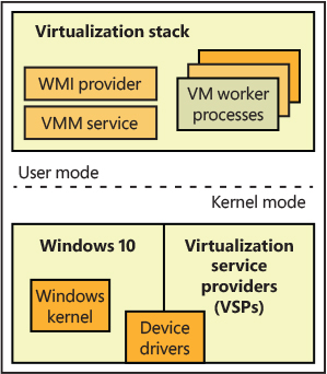
Figure 9-2 Components of the root partition.
Child partitions
A child partition is an instance of any operating system running parallel to the parent partition. (Because you can save or pause the state of any child, it might not necessarily be running.) Unlike the parent partition, which has full access to the APIC, I/O ports, and its physical memory (but not access to the hypervisor’s and Secure Kernel’s physical memory), child partitions are limited for security and management reasons to their own view of address space (the Guest Physical Address, or GPA, space, which is managed by the hypervisor) and have no direct access to hardware (even though they may have direct access to certain kinds of devices; see the “Virtualization stack” section for further details). In terms of hypervisor access, a child partition is also limited mainly to notifications and state changes. For example, a child partition doesn’t have control over other partitions (and can’t create new ones).
Child partitions have many fewer virtualization components than a parent partition because they aren’t responsible for running the virtualization stack—only for communicating with it. Also, these components can also be considered optional because they enhance performance of the environment but aren’t critical to its use. Figure 9-3 shows the components present in a typical Windows child partition.
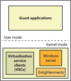
Figure 9-3 Components of a child partition.
Processes and threads
The Windows hypervisor represents a virtual machine with a partition data structure. A partition, as described in the previous section, is composed of some memory (guest physical memory) and one or more virtual processors (VP). Internally in the hypervisor, each virtual processor is a schedulable entity, and the hypervisor, like the standard NT kernel, includes a scheduler. The scheduler dispatches the execution of virtual processors, which belong to different partitions, to each physical CPU. (We discuss the multiple types of hypervisor schedulers later in this chapter in the “Hyper-V schedulers” section.) A hypervisor thread (TH_THREAD data structure) is the glue between a virtual processor and its schedulable unit. Figure 9-4 shows the data structure, which represents the current physical execution context. It contains the thread execution stack, scheduling data, a pointer to the thread’s virtual processor, the entry point of the thread dispatch loop (discussed later) and, most important, a pointer to the hypervisor process that the thread belongs to.
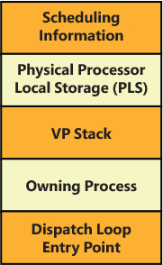
Figure 9-4 The hypervisor’s thread data structure.
The hypervisor builds a thread for each virtual processor it creates and associates the newborn thread with the virtual processor data structure (VM_VP).
A hypervisor process (TH_PROCESS data structure), shown in Figure 9-5, represents a partition and is a container for its physical (and virtual) address space. It includes the list of the threads (which are backed by virtual processors), scheduling data (the physical CPUs affinity in which the process is allowed to run), and a pointer to the partition basic memory data structures (memory compartment, reserved pages, page directory root, and so on). A process is usually created when the hypervisor builds the partition (VM_PARTITION data structure), which will represent the new virtual machine.
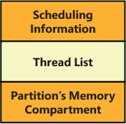
Figure 9-5 The hypervisor’s process data structure.
Enlightenments
Enlightenments are one of the key performance optimizations that Windows virtualization takes advantage of. They are direct modifications to the standard Windows kernel code that can detect that the operating system is running in a child partition and perform work differently. Usually, these optimizations are highly hardware-specific and result in a hypercall to notify the hypervisor.
An example is notifying the hypervisor of a long busy–wait spin loop. The hypervisor can keep some state on the spin wait and decide to schedule another VP on the same physical processor until the wait can be satisfied. Entering and exiting an interrupt state and access to the APIC can be coordinated with the hypervisor, which can be enlightened to avoid trapping the real access and then virtualizing it.
Another example has to do with memory management, specifically translation lookaside buffer (TLB) flushing. (See Part 1, Chapter 5, “Memory management,” for more information on these concepts.) Usually, the operating system executes a CPU instruction to flush one or more stale TLB entries, which affects only a single processor. In multiprocessor systems, usually a TLB entry must be flushed from every active processor’s cache (the system sends an inter-processor interrupt to every active processor to achieve this goal). However, because a child partition could be sharing physical CPUs with many other child partitions, and some of them could be executing a different VM’s virtual processor at the time the TLB flush is initiated, such an operation would also flush this information for those VMs. Furthermore, a virtual processor would be rescheduled to execute only the TLB flushing IPI, resulting in noticeable performance degradation. If Windows is running under a hypervisor, it instead issues a hypercall to have the hypervisor flush only the specific information belonging to the child partition.
Partition’s privileges, properties, and version features
When a partition is initially created (usually by the VID driver), no virtual processors (VPs) are associated with it. At that time, the VID driver is free to add or remove some partition’s privileges. Indeed, when the partition is first created, the hypervisor assigns some default privileges to it, depending on its type.
A partition’s privilege describes which action—usually expressed through hypercalls or synthetic MSRs (model specific registers)—the enlightened OS running inside a partition is allowed to perform on behalf of the partition itself. For example, the Access Root Scheduler privilege allows a child partition to notify the root partition that an event has been signaled and a guest’s VP can be rescheduled (this usually increases the priority of the guest’s VP-backed thread). The Access VSM privilege instead allows the partition to enable VTL 1 and access its properties and configuration (usually exposed through synthetic registers). Table 9-1 lists all the privileges assigned by default by the hypervisor.
Table 9-1 Partition’s privileges
PARTITION TYPE |
DEFAULT PRIVILEGES |
|---|---|
Root and child partition |
Read/write a VP’s runtime counter Read the current partition reference time Access SynIC timers and registers Query/set the VP’s virtual APIC assist page Read/write hypercall MSRs Request VP IDLE entry Read VP’s index Map or unmap the hypercall’s code area Read a VP’s emulated TSC (time-stamp counter) and its frequency Control the partition TSC and re-enlightenment emulation Read/write VSM synthetic registers Read/write VP’s per-VTL registers Starts an AP virtual processor Enables partition’s fast hypercall support |
Root partition only |
Create child partition Look up and reference a partition by ID Deposit/withdraw memory from the partition compartment Post messages to a connection port Signal an event in a connection port’s partition Create/delete and get properties of a partition’s connection port Connect/disconnect to a partition’s connection port Map/unmap the hypervisor statistics page (which describe a VP, LP, partition, or hypervisor) Enable the hypervisor debugger for the partition Schedule child partition’s VPs and access SynIC synthetic MSRs Trigger an enlightened system reset Read the hypervisor debugger options for a partition |
Child partition only |
Generate an extended hypercall intercept in the root partition Notify a root scheduler’s VP-backed thread of an event being signaled |
EXO partition |
None |
Partition privileges can only be set before the partition creates and starts any VPs; the hypervisor won’t allow requests to set privileges after a single VP in the partition starts to execute. Partition properties are similar to privileges but do not have this limitation; they can be set and queried at any time. There are different groups of properties that can be queried or set for a partition. Table 9-2 lists the properties groups.
Table 9-2 Partition’s properties
PROPERTY GROUP |
DESCRIPTION |
|---|---|
Scheduling properties |
Set/query properties related to the classic and core scheduler, like Cap, Weight, and Reserve |
Time properties |
Allow the partition to be suspended/resumed |
Debugging properties |
Change the hypervisor debugger runtime configuration |
Resource properties |
Queries virtual hardware platform-specific properties of the partition (like TLB size, SGX support, and so on) |
Compatibility properties |
Queries virtual hardware platform-specific properties that are tied to the initial compatibility features |
When a partition is created, the VID infrastructure provides a compatibility level (which is specified in the virtual machine’s configuration file) to the hypervisor. Based on that compatibility level, the hypervisor enables or disables specific virtual hardware features that could be exposed by a VP to the underlying OS. There are multiple features that tune how the VP behaves based on the VM’s compatibility level. A good example would be the hardware Page Attribute Table (PAT), which is a configurable caching type for virtual memory. Prior to Windows 10 Anniversary Update (RS1), guest VMs weren’t able to use PAT in guest VMs, so regardless of whether the compatibility level of a VM specifies Windows 10 RS1, the hypervisor will not expose the PAT registers to the underlying guest OS. Otherwise, in case the compatibility level is higher than Windows 10 RS1, the hypervisor exposes the PAT support to the underlying OS running in the guest VM. When the root partition is initially created at boot time, the hypervisor enables the highest compatibility level for it. In that way the root OS can use all the features supported by the physical hardware.
The hypervisor startup
In Chapter 12, we analyze the modality in which a UEFI-based workstation boots up, and all the components engaged in loading and starting the correct version of the hypervisor binary. In this section, we briefly discuss what happens in the machine after the HvLoader module has transferred the execution to the hypervisor, which takes control for the first time.
The HvLoader loads the correct version of the hypervisor binary image (depending on the CPU manufacturer) and creates the hypervisor loader block. It captures a minimal processor context, which the hypervisor needs to start the first virtual processor. The HvLoader then switches to a new, just-created, address space and transfers the execution to the hypervisor image by calling the hypervisor image entry point, KiSystemStartup, which prepares the processor for running the hypervisor and initializes the CPU_PLS data structure. The CPU_PLS represents a physical processor and acts as the PRCB data structure of the NT kernel; the hypervisor is able to quickly address it (using the GS segment). Differently from the NT kernel, KiSystemStartup is called only for the boot processor (the application processors startup sequence is covered in the “Application Processors (APs) Startup” section later in this chapter), thus it defers the real initialization to another function, BmpInitBootProcessor.
BmpInitBootProcessor starts a complex initialization sequence. The function examines the system and queries all the CPU’s supported virtualization features (such as the EPT and VPID; the queried features are platform-specific and vary between the Intel, AMD, or ARM version of the hypervisor). It then determines the hypervisor scheduler, which will manage how the hypervisor will schedule virtual processors. For Intel and AMD server systems, the default scheduler is the core scheduler, whereas the root scheduler is the default for all client systems (including ARM64). The scheduler type can be manually overridden through the hypervisorschedulertype BCD option (more information about the different hypervisor schedulers is available later in this chapter).
The nested enlightenments are initialized. Nested enlightenments allow the hypervisor to be executed in nested configurations, where a root hypervisor (called L0 hypervisor), manages the real hardware, and another hypervisor (called L1 hypervisor) is executed in a virtual machine. After this stage, the BmpInitBootProcessor routine performs the initialization of the following components:
Memory manager (initializes the PFN database and the root compartment).
The hypervisor’s hardware abstraction layer (HAL).
The hypervisor’s process and thread subsystem (which depends on the chosen scheduler type). The system process and its initial thread are created. This process is special; it isn’t tied to any partition and hosts threads that execute the hypervisor code.
The VMX virtualization abstraction layer (VAL). The VAL’s purpose is to abstract differences between all the supported hardware virtualization extensions (Intel, AMD, and ARM64). It includes code that operates on platform-specific features of the machine’s virtualization technology in use by the hypervisor (for example, on the Intel platform the VAL layer manages the “unrestricted guest” support, the EPT, SGX, MBEC, and so on).
The Synthetic Interrupt Controller (SynIC) and I/O Memory Management Unit (IOMMU).
The Address Manager (AM), which is the component responsible for managing the physical memory assigned to a partition (called guest physical memory, or GPA) and its translation to real physical memory (called system physical memory). Although the first implementation of Hyper-V supported shadow page tables (a software technique for address translation), since Windows 8.1, the Address manager uses platform-dependent code for configuring the hypervisor address translation mechanism offered by the hardware (extended page tables for Intel, nested page tables for AMD). In hypervisor terms, the physical address space of a partition is called address domain. The platform-independent physical address space translation is commonly called Second Layer Address Translation (SLAT). The term refers to the Intel’s EPT, AMD’s NPT or ARM 2-stage address translation mechanism.
The hypervisor can now finish constructing the CPU_PLS data structure associated with the boot processor by allocating the initial hardware-dependent virtual machine control structures (VMCS for Intel, VMCB for AMD) and by enabling virtualization through the first VMXON operation. Finally, the per-processor interrupt mapping data structures are initialized.
EXPERIMENT: CONNECTING THE HYPERVISOR DEBUGGER
In this experiment, you will connect the hypervisor debugger for analyzing the startup sequence of the hypervisor, as discussed in the previous section. The hypervisor debugger is supported only via serial or network transports. Only physical machines can be used to debug the hypervisor, or virtual machines in which the “nested virtualization” feature is enabled (see the “Nested virtualization” section later in this chapter). In the latter case, only serial debugging can be enabled for the L1 virtualized hypervisor.
For this experiment, you need a separate physical machine that supports virtualization extensions and has the Hyper-V role installed and enabled. You will use this machine as the debugged system, attached to your host system (which acts as the debugger) where you are running the debugging tools. As an alternative, you can set up a nested VM, as shown in the “Enabling nested virtualization on Hyper-V” experiment later in this chapter (in that case you don’t need another physical machine).
As a first step, you need to download and install the “Debugging Tools for Windows” in the host system, which are available as part of the Windows SDK (or WDK), downloadable from https://developer.microsoft.com/en-us/windows/downloads/windows-10-sdk. As an alternative, for this experiment you also can use the WinDbgX, which, at the time of this writing, is available in the Windows Store by searching “WinDbg Preview.”
The debugged system for this experiment must have Secure Boot disabled. The hypervisor debugging is not compatible with Secure Boot. Refer to your workstation user manual for understanding how to disable Secure Boot (usually the Secure Boot settings are located in the UEFI Bios). For enabling the hypervisor debugger in the debugged system, you should first open an administrative command prompt (by typing cmd in the Cortana search box and selecting Run as administrator).
In case you want to debug the hypervisor through your network card, you should type the following commands, replacing the terms <HostIp> with the IP address of the host system; <HostPort>” with a valid port in the host (from 49152); and <NetCardBusParams> with the bus parameters of the network card of the debugged system, specified in the XX.YY.ZZ format (where XX is the bus number, YY is the device number, and ZZ is the function number). You can discover the bus parameters of your network card through the Device Manager applet or through the KDNET.exe tool available in the Windows SDK:
bcdedit /hypervisorsettings net hostip:<HostIp> port:<HostPort>
bcdedit /set {hypervisorsettings} hypervisordebugpages 1000
bcdedit /set {hypervisorsettings} hypervisorbusparams <NetCardBusParams>
bcdedit /set hypervisordebug on
The following figure shows a sample system in which the network interface used for debugging the hypervisor is located in the 0.25.0 bus parameters, and the debugger is targeting a host system configured with the IP address 192.168.0.56 on the port 58010.
)
Take note of the returned debugging key. After you reboot the debugged system, you should run Windbg in the host, with the following command:
windbg.exe -d -k net:port=<HostPort>,key=<DebuggingKey>
You should be able to debug the hypervisor, and follow its startup sequence, even though Microsoft may not release the symbols for the main hypervisor module:
)
In a VM with nested virtualization enabled, you can enable the L1 hypervisor debugger only through the serial port by using the following command in the debugged system:
bcdedit /hypervisorsettings SERIAL DEBUGPORT:1 BAUDRATE:115200
The creation of the root partition and the boot virtual processor
The first steps that a fully initialized hypervisor needs to execute are the creation of the root partition and the first virtual processor used for starting the system (called BSP VP). Creating the root partition follows almost the same rules as for child partitions; multiple layers of the partition are initialized one after the other. In particular:
The VM-layer initializes the maximum allowed number of VTL levels and sets up the partition privileges based on the partition’s type (see the previous section for more details). Furthermore, the VM layer determines the partition’s allowable features based on the specified partition’s compatibility level. The root partition supports the maximum allowable features.
The VP layer initializes the virtualized CPUID data, which all the virtual processors of the partition use when a CPUID is requested from the guest operating system. The VP layer creates the hypervisor process, which backs the partition.
The Address Manager (AM) constructs the partition’s initial physical address space by using machine platform-dependent code (which builds the EPT for Intel, NPT for AMD). The constructed physical address space depends on the partition type. The root partition uses identity mapping, which means that all the guest physical memory corresponds to the system physical memory (more information is provided later in this chapter in the “Partitions’ physical address space” section).
Finally, after the SynIC, IOMMU, and the intercepts’ shared pages are correctly configured for the partition, the hypervisor creates and starts the BSP virtual processor for the root partition, which is the unique one used to restart the boot process.
A hypervisor virtual processor (VP) is represented by a big data structure (VM_VP), shown in Figure 9-6. A VM_VP data structure maintains all the data used to track the state of the virtual processor: its platform-dependent registers state (like general purposes, debug, XSAVE area, and stack) and data, the VP’s private address space, and an array of VM_VPLC data structures, which are used to track the state of each Virtual Trust Level (VTL) of the virtual processor. The VM_VP also includes a pointer to the VP’s backing thread and a pointer to the physical processor that is currently executing the VP.

Figure 9-6 The VM_VP data structure representing a virtual processor.
As for the partitions, creating the BSP virtual processor is similar to the process of creating normal virtual processors. VmAllocateVp is the function responsible in allocating and initializing the needed memory from the partition’s compartment, used for storing the VM_VP data structure, its platform-dependent part, and the VM_VPLC array (one for each supported VTL). The hypervisor copies the initial processor context, specified by the HvLoader at boot time, into the VM_VP structure and then creates the VP’s private address space and attaches to it (only in case address space isolation is enabled). Finally, it creates the VP’s backing thread. This is an important step: the construction of the virtual processor continues in the context of its own backing thread. The hypervisor’s main system thread at this stage waits until the new BSP VP is completely initialized. The wait brings the hypervisor scheduler to select the newly created thread, which executes a routine, ObConstructVp, that constructs the VP in the context of the new backed thread.
ObConstructVp, in a similar way as for partitions, constructs and initializes each layer of the virtual processor—in particular, the following:
The Virtualization Manager (VM) layer attaches the physical processor data structure (CPU_PLS) to the VP and sets VTL 0 as active.
The VAL layer initializes the platform-dependent portions of the VP, like its registers, XSAVE area, stack, and debug data. Furthermore, for each supported VTL, it allocates and initializes the VMCS data structure (VMCB for AMD systems), which is used by the hardware for keeping track of the state of the virtual machine, and the VTL’s SLAT page tables. The latter allows each VTL to be isolated from each other (more details about VTLs are provided later in the “Virtual Trust Levels (VTLs) and Virtual Secure Mode (VSM)” section) . Finally, the VAL layer enables and sets VTL 0 as active. The platform-specific VMCS (or VMCB for AMD systems) is entirely compiled, the SLAT table of VTL 0 is set as active, and the real-mode emulator is initialized. The Host-state part of the VMCS is set to target the hypervisor VAL dispatch loop. This routine is the most important part of the hypervisor because it manages all the VMEXIT events generated by each guest.
The VP layer allocates the VP’s hypercall page, and, for each VTL, the assist and intercept message pages. These pages are used by the hypervisor for sharing code or data with the guest operating system.
When ObConstructVp finishes its work, the VP’s dispatch thread activates the virtual processor and its synthetic interrupt controller (SynIC). If the VP is the first one of the root partition, the dispatch thread restores the initial VP’s context stored in the VM_VP data structure by writing each captured register in the platform-dependent VMCS (or VMCB) processor area (the context has been specified by the HvLoader earlier in the boot process). The dispatch thread finally signals the completion of the VP initialization (as a result, the main system thread enters the idle loop) and enters the platform-dependent VAL dispatch loop. The VAL dispatch loop detects that the VP is new, prepares it for the first execution, and starts the new virtual machine by executing a VMLAUNCH instruction. The new VM restarts exactly at the point at which the HvLoader has transferred the execution to the hypervisor. The boot process continues normally but in the context of the new hypervisor partition.
The hypervisor memory manager
The hypervisor memory manager is relatively simple compared to the memory manager for NT or the Secure Kernel. The entity that manages a set of physical memory pages is the hypervisor’s memory compartment. Before the hypervisor startup takes palace, the hypervisor loader (Hvloader.dll) allocates the hypervisor loader block and pre-calculates the maximum number of physical pages that will be used by the hypervisor for correctly starting up and creating the root partition. The number depends on the pages used to initialize the IOMMU to store the memory range structures, the system PFN database, SLAT page tables, and HAL VA space. The hypervisor loader preallocates the calculated number of physical pages, marks them as reserved, and attaches the page list array in the loader block. Later, when the hypervisor starts, it creates the root compartment by using the page list that was allocated by the hypervisor loader.
Figure 9-7 shows the layout of the memory compartment data structure. The data structure keeps track of the total number of physical pages “deposited” in the compartment, which can be allocated somewhere or freed. A compartment stores its physical pages in different lists ordered by the NUMA node. Only the head of each list is stored in the compartment. The state of each physical page and its link in the NUMA list is maintained thanks to the entries in the PFN database. A compartment also tracks its relationship with the root. A new compartment can be created using the physical pages that belongs to the parent (the root). Similarly, when the compartment is deleted, all its remaining physical pages are returned to the parent.
)
Figure 9-7 The hypervisor’s memory compartment. Virtual address space for the global zone is reserved from the end of the compartment data structure
When the hypervisor needs some physical memory for any kind of work, it allocates from the active compartment (depending on the partition). This means that the allocation can fail. Two possible scenarios can arise in case of failure:
If the allocation has been requested for a service internal to the hypervisor (usually on behalf of the root partition), the failure should not happen, and the system is crashed. (This explains why the initial calculation of the total number of pages to be assigned to the root compartment needs to be accurate.)
If the allocation has been requested on behalf of a child partition (usually through a hypercall), the hypervisor will fail the request with the status INSUFFICIENT_MEMORY. The root partition detects the error and performs the allocation of some physical page (more details are discussed later in the “Virtualization stack” section), which will be deposited in the child compartment through the HvDepositMemory hypercall. The operation can be finally reinitiated (and usually will succeed).
The physical pages allocated from the compartment are usually mapped in the hypervisor using a virtual address. When a compartment is created, a virtual address range (sized 4 or 8 GB, depending on whether the compartment is a root or a child) is allocated with the goal of mapping the new compartment, its PDE bitmap, and its global zone.
A hypervisor’s zone encapsulates a private VA range, which is not shared with the entire hypervisor address space (see the “Isolated address space” section later in this chapter). The hypervisor executes with a single root page table (differently from the NT kernel, which uses KVA shadowing). Two entries in the root page table page are reserved with the goal of dynamically switching between each zone and the virtual processors’ address spaces.
Partitions’ physical address space
As discussed in the previous section, when a partition is initially created, the hypervisor allocates a physical address space for it. A physical address space contains all the data structures needed by the hardware to translate the partition’s guest physical addresses (GPAs) to system physical addresses (SPAs). The hardware feature that enables the translation is generally referred to as second level address translation (SLAT). The term SLAT is platform-agnostic: hardware vendors use different names: Intel calls it EPT for extended page tables; AMD uses the term NPT for nested page tables; and ARM simply calls it Stage 2 Address Translation.
The SLAT is usually implemented in a way that’s similar to the implementation of the x64 page tables, which uses four levels of translation (the x64 virtual address translation has already been discussed in detail in Chapter 5 of Part 1). The OS running inside the partition uses the same virtual address translation as if it were running by bare-metal hardware. However, in the former case, the physical processor actually executes two levels of translation: one for virtual addresses and one for translating physical addresses. Figure 9-8 shows the SLAT set up for a guest partition. In a guest partition, a GPA is usually translated to a different SPA. This is not true for the root partition.
)
Figure 9-8 Address translation for a guest partition.
When the hypervisor creates the root partition, it builds its initial physical address space by using identity mapping. In this model, each GPA corresponds to the same SPA (for example, guest frame 0x1000 in the root partition is mapped to the bare-metal physical frame 0x1000). The hypervisor preallocates the memory needed for mapping the entire physical address space of the machine (which has been discovered by the Windows Loader using UEFI services; see Chapter 12 for details) into all the allowed root partition’s virtual trust levels (VTLs). (The root partition usually supports two VTLs.) The SLAT page tables of each VTL belonging to the partition include the same GPA and SPA entries but usually with a different protection level set. The protection level applied to each partition’s physical frame allows the creation of different security domains (VTL), which can be isolated one from each other. VTLs are explained in detail in the section “The Secure Kernel” later in this chapter. The hypervisor pages are marked as hardware-reserved and are not mapped in the partition’s SLAT table (actually they are mapped using an invalid entry pointing to a dummy PFN).
 NOTE
NOTE
For performance reasons, the hypervisor, while building the physical memory mapping, is able to detect large chunks of contiguous physical memory, and, in a similar way as for virtual memory, is able to map those chunks by using large pages. If for some reason the OS running in the partition decides to apply a more granular protection to the physical page, the hypervisor would use the reserved memory for breaking the large page in the SLAT table.
Earlier versions of the hypervisor also supported another technique for mapping a partition’s physical address space: shadow paging. Shadow paging was used for those machines without the SLAT support. This technique had a very high-performance overhead; as a result, it’s not supported anymore. (The machine must support SLAT; otherwise, the hypervisor would refuse to start.)
The SLAT table of the root is built at partition-creation time, but for a guest partition, the situation is slightly different. When a child partition is created, the hypervisor creates its initial physical address space but allocates only the root page table (PML4) for each partition’s VTL. Before starting the new VM, the VID driver (part of the virtualization stack) reserves the physical pages needed for the VM (the exact number depends on the VM memory size) by allocating them from the root partition. (Remember, we are talking about physical memory; only a driver can allocate physical pages.) The VID driver maintains a list of physical pages, which is analyzed and split in large pages and then is sent to the hypervisor through the HvMapGpaPages Rep hypercall.
Before sending the map request, the VID driver calls into the hypervisor for creating the needed SLAT page tables and internal physical memory space data structures. Each SLAT page table hierarchy is allocated for each available VTL in the partition (this operation is called pre-commit). The operation can fail, such as when the new partition’s compartment could not contain enough physical pages. In this case, as discussed in the previous section, the VID driver allocates more memory from the root partition and deposits it in the child’s partition compartment. At this stage, the VID driver can freely map all the child’s partition physical pages. The hypervisor builds and compiles all the needed SLAT page tables, assigning different protection based on the VTL level. (Large pages require one less indirection level.) This step concludes the child partition’s physical address space creation.
Address space isolation
Speculative execution vulnerabilities discovered in modern CPUs (also known as Meltdown, Spectre, and Foreshadow) allowed an attacker to read secret data located in a more privileged execution context by speculatively reading the stale data located in the CPU cache. This means that software executed in a guest VM could potentially be able to speculatively read private memory that belongs to the hypervisor or to the more privileged root partition. The internal details of the Spectre, Meltdown, and all the side-channel vulnerabilities and how they are mitigated by Windows have been covered in detail in Chapter 8.
The hypervisor has been able to mitigate most of these kinds of attacks by implementing the HyperClear mitigation. The HyperClear mitigation relies on three key components to ensure strong Inter-VM isolation: core scheduler, Virtual-Processor Address Space Isolation, and sensitive data scrubbing. In modern multicore CPUs, often different SMT threads share the same CPU cache. (Details about the core scheduler and symmetric multithreading are provided in the “Hyper-V schedulers” section.) In the virtualization environment, SMT threads on a core can independently enter and exit the hypervisor context based on their activity. For example, events like interrupts can cause an SMT thread to switch out of running the guest virtual processor context and begin executing the hypervisor context. This can happen independently for each SMT thread, so one SMT thread may be executing in the hypervisor context while its sibling SMT thread is still running a VM’s guest virtual processor context. An attacker running code in a less trusted guest VM’s virtual processor context on one SMT thread can then use a side channel vulnerability to potentially observe sensitive data from the hypervisor context running on the sibling SMT thread.
The hypervisor provides strong data isolation to protect against a malicious guest VM by maintaining separate virtual address ranges for each guest SMT thread (which back a virtual processor). When the hypervisor context is entered on a specific SMT thread, no secret data is addressable. The only data that can be brought into the CPU cache is associated with that current guest virtual processor or represent shared hypervisor data. As shown in Figure 9-9, when a VP running on an SMT thread enters the hypervisor, it is enforced (by the root scheduler) that the sibling LP is running another VP that belongs to the same VM. Furthermore, no shared secrets are mapped in the hypervisor. In case the hypervisor needs to access secret data, it assures that no other VP is scheduled in the other sibling SMT thread.
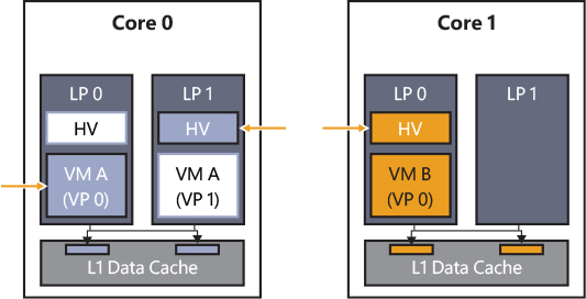
Figure 9-9 The Hyperclear mitigation.
Unlike the NT kernel, the hypervisor always runs with a single page table root, which creates a single global virtual address space. The hypervisor defines the concept of private address space, which has a misleading name. Indeed, the hypervisor reserves two global root page table entries (PML4 entries, which generate a 1-TB virtual address range) for mapping or unmapping a private address space. When the hypervisor initially constructs the VP, it allocates two private page table root entries. Those will be used to map the VP’s secret data, like its stack and data structures that contain private data. Switching the address space means writing the two entries in the global page table root (which explains why the term private address space has a misleading name—actually it is private address range). The hypervisor switches private address spaces only in two cases: when a new virtual processor is created and during thread switches. (Remember, threads are backed by VPs. The core scheduler assures that no sibling SMT threads execute VPs from different partitions.) During runtime, a hypervisor thread has mapped only its own VP’s private data; no other secret data is accessible by that thread.
Mapping secret data in the private address space is achieved by using the memory zone, represented by an MM_ZONE data structure. A memory zone encapsulates a private VA subrange of the private address space, where the hypervisor usually stores per-VP’s secrets.
The memory zone works similarly to the private address space. Instead of mapping root page table entries in the global page table root, a memory zone maps private page directories in the two root entries used by the private address space. A memory zone maintains an array of page directories, which will be mapped and unmapped into the private address space, and a bitmap that keeps track of the used page tables. Figure 9-10 shows the relationship between a private address space and a memory zone. Memory zones can be mapped and unmapped on demand (in the private address space) but are usually switched only at VP creation time. Indeed, the hypervisor does not need to switch them during thread switches; the private address space encapsulates the VA range exposed by the memory zone.
)
Figure 9-10 The hypervisor’s private address spaces and private memory zones.
In Figure 9-10, the page table’s structures related to the private address space are filled with a pattern, the ones related to the memory zone are shown in gray, and the shared ones belonging to the hypervisor are drawn with a dashed line. Switching private address spaces is a relatively cheap operation that requires the modification of two PML4 entries in the hypervisor’s page table root. Attaching or detaching a memory zone from the private address space requires only the modification of the zone’s PDPTE (a zone VA size is variable; the PDTPE are always allocated contiguously).
Dynamic memory
Virtual machines can use a different percentage of their allocated physical memory. For example, some virtual machines use only a small amount of their assigned guest physical memory, keeping a lot of it freed or zeroed. The performance of other virtual machines can instead suffer for high-memory pressure scenarios, where the page file is used too often because the allocated guest physical memory is not enough. With the goal to prevent the described scenario, the hypervisor and the virtualization stack supports the concept of dynamic memory. Dynamic memory is the ability to dynamically assign and remove physical memory to a virtual machine. The feature is provided by multiple components:
The NT kernel’s memory manager, which supports hot add and hot removal of physical memory (on bare-metal system too)
The hypervisor, through the SLAT (managed by the address manager)
The VM Worker process, which uses the dynamic memory controller module, Vmdynmem.dll, to establish a connection to the VMBus Dynamic Memory VSC driver (Dmvsc.sys), which runs in the child partition
To properly describe dynamic memory, we should quickly introduce how the page frame number (PFN) database is created by the NT kernel. The PFN database is used by Windows to keep track of physical memory. It was discussed in detail in Chapter 5 of Part 1. For creating the PFN database, the NT kernel first calculates the hypothetical size needed to map the highest possible physical address (256 TB on standard 64-bit systems) and then marks the VA space needed to map it entirely as reserved (storing the base address to the MmPfnDatabase global variable). Note that the reserved VA space still has no page tables allocated. The NT kernel cycles between each physical memory descriptor discovered by the boot manager (using UEFI services), coalesces them in the longest ranges possible and, for each range, maps the underlying PFN database entries using large pages. This has an important implication; as shown in Figure 9-11, the PFN database has space for the highest possible amount of physical memory but only a small subset of it is mapped to real physical pages (this technique is called sparse memory).
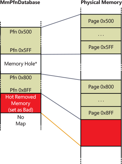
Figure 9-11 An example of a PFN database where some physical memory has been removed.
Hot add and removal of physical memory works thanks to this principle. When new physical memory is added to the system, the Plug and Play memory driver (Pnpmem.sys) detects it and calls the MmAddPhysicalMemory routine, which is exported by the NT kernel. The latter starts a complex procedure that calculates the exact number of pages in the new range and the Numa node to which they belong, and then it maps the new PFN entries in the database by creating the necessary page tables in the reserved VA space. The new physical pages are added to the free list (see Chapter 5 in Part 1 for more details).
When some physical memory is hot removed, the system performs an inverse procedure. It checks that the pages belong to the correct physical page list, updates the internal memory counters (like the total number of physical pages), and finally frees the corresponding PFN entries, meaning that they all will be marked as “bad.” The memory manager will never use the physical pages described by them anymore. No actual virtual space is unmapped from the PFN database. The physical memory that was described by the freed PFNs can always be re-added in the future.
When an enlightened VM starts, the dynamic memory driver (Dmvsc.sys) detects whether the child VM supports the hot add feature; if so, it creates a worker thread that negotiates the protocol and connects to the VMBus channel of the VSP. (See the “Virtualization stack” section later in this chapter for details about VSC and VSP.) The VMBus connection channel connects the dynamic memory driver running in the child partition to the dynamic memory controller module (Vmdynmem.dll), which is mapped in the VM Worker process in the root partition. A message exchange protocol is started. Every one second, the child partition acquires a memory pressure report by querying different performance counters exposed by the memory manager (global page-file usage; number of available, committed, and dirty pages; number of page faults per seconds; number of pages in the free and zeroed page list). The report is then sent to the root partition.
The VM Worker process in the root partition uses the services exposed by the VMMS balancer, a component of the VmCompute service, for performing the calculation needed for determining the possibility to perform a hot add operation. If the memory status of the root partition allowed a hot add operation, the VMMS balancer calculates the proper number of pages to deposit in the child partition and calls back (through COM) the VM Worker process, which starts the hot add operation with the assistance of the VID driver:
Reserves the proper amount of physical memory in the root partition
Calls the hypervisor with the goal to map the system physical pages reserved by the root partition to some guest physical pages mapped in the child VM, with the proper protection
Sends a message to the dynamic memory driver for starting a hot add operation on some guest physical pages previously mapped by the hypervisor
The dynamic memory driver in the child partition uses the MmAddPhysicalMemory API exposed by the NT kernel to perform the hot add operation. The latter maps the PFNs describing the new guest physical memory in the PFN database, adding new backing pages to the database if needed.
In a similar way, when the VMMS balancer detects that the child VM has plenty of physical pages available, it may require the child partition (still through the VM Worker process) to hot remove some physical pages. The dynamic memory driver uses the MmRemovePhysicalMemory API to perform the hot remove operation. The NT kernel verifies that each page in the range specified by the balancer is either on the zeroed or free list, or it belongs to a stack that can be safely paged out. If all the conditions apply, the dynamic memory driver sends back the “hot removal” page range to the VM Worker process, which will use services provided by the VID driver to unmap the physical pages from the child partition and release them back to the NT kernel.
NOTE
Dynamic memory is not supported when nested virtualization is enabled.
Hyper-V schedulers
The hypervisor is a kind of micro operating system that runs below the root partition’s OS (Windows). As such, it should be able to decide which thread (backing a virtual processor) is being executed by which physical processor. This is especially true when the system runs multiple virtual machines composed in total by more virtual processors than the physical processors installed in the workstation. The hypervisor scheduler role is to select the next thread that a physical CPU is executing after the allocated time slice of the current one ends. Hyper-V can use three different schedulers. To properly manage all the different schedulers, the hypervisor exposes the scheduler APIs, a set of routines that are the only entries into the hypervisor scheduler. Their sole purpose is to redirect API calls to the particular scheduler implementation.
EXPERIMENT: CONTROLLING THE HYPERVISOR’S SCHEDULER TYPE
Whereas client editions of Windows start by default with the root scheduler, Windows Server 2019 runs by default with the core scheduler. In this experiment, you figure out the hypervisor scheduler enabled on your system and find out how to switch to another kind of hypervisor scheduler on the next system reboot.
The Windows hypervisor logs a system event after it has determined which scheduler to enable. You can search the logged event by using the Event Viewer tool, which you can run by typing eventvwr in the Cortana search box. After the applet is started, expand the Windows Logs key and click the System log. You should search for events with ID 2 and the Event sources set to Hyper-V-Hypervisor. You can do that by clicking the Filter Current Log button located on the right of the window or by clicking the Event ID column, which will order the events in ascending order by their ID (keep in mind that the operation can take a while). If you double-click a found event, you should see a window like the following:
)
The launch event ID 2 denotes indeed the hypervisor scheduler type, where
1 = Classic scheduler, SMT disabled
2 = Classic scheduler
3 = Core scheduler
4 = Root scheduler
The sample figure was taken from a Windows Server system, which runs by default with the Core Scheduler. To change the scheduler type to the classic one (or root), you should open an administrative command prompt window (by typing cmd in the Cortana search box and selecting Run As Administrator) and type the following command:
bcdedit /set hypervisorschedulertype <Type>
where <Type> is Classic for the classic scheduler, Core for the core scheduler, or Root for the root scheduler. You should restart the system and check again the newly generated Hyper-V-Hypervisor event ID 2. You can also check the current enabled hypervisor scheduler by using an administrative PowerShell window with the following command:
Get-WinEvent -FilterHashTable @{ProviderName="Microsoft-Windows-Hyper-V-Hypervisor"; ID=2}
-MaxEvents 1
The command extracts the last Event ID 2 from the System event log.
)
)
)
)
)
)
)
)
The classic scheduler
The classic scheduler has been the default scheduler used on all versions of Hyper-V since its initial release. The classic scheduler in its default configuration implements a simple, round-robin policy in which any virtual processor in the current execution state (the execution state depends on the total number of VMs running in the system) is equally likely to be dispatched. The classic scheduler supports also setting a virtual processor’s affinity and performs scheduling decisions considering the physical processor’s NUMA node. The classic scheduler doesn’t know what a guest VP is currently executing. The only exception is defined by the spin-lock enlightenment. When the Windows kernel, which is running in a partition, is going to perform an active wait on a spin-lock, it emits a hypercall with the goal to inform the hypervisor (high IRQL synchronization mechanisms are described in Chapter 8, “System mechanisms”). The classic scheduler can preempt the current executing virtual processor (which hasn’t expired its allocated time slice yet) and can schedule another one. In this way it saves the active CPU spin cycles.
The default configuration of the classic scheduler assigns an equal time slice to each VP. This means that in high-workload oversubscribed systems, where multiple virtual processors attempt to execute, and the physical processors are sufficiently busy, performance can quickly degrade. To overcome the problem, the classic scheduler supports different fine-tuning options (see Figure 9-12), which can modify its internal scheduling decision:
VP reservations A user can reserve the CPU capacity in advance on behalf of a guest machine. The reservation is specified as the percentage of the capacity of a physical processor to be made available to the guest machine whenever it is scheduled to run. As a result, Hyper-V schedules the VP to run only if that minimum amount of CPU capacity is available (meaning that the allocated time slice is guaranteed).
VP limits Similar to VP reservations, a user can limit the percentage of physical CPU usage for a VP. This means reducing the available time slice allocated to a VP in a high workload scenario.
VP weight This controls the probability that a VP is scheduled when the reservations have already been met. In default configurations, each VP has an equal probability of being executed. When the user configures weight on the VPs that belong to a virtual machine, scheduling decisions become based on the relative weighting factor the user has chosen. For example, let’s assume that a system with four CPUs runs three virtual machines at the same time. The first VM has set a weighting factor of 100, the second 200, and the third 300. Assuming that all the system’s physical processors are allocated to a uniform number of VPs, the probability of a VP in the first VM to be dispatched is 17%, of a VP in the second VM is 33%, and of a VP in the third one is 50%.
)
Figure 9-12 The classic scheduler fine-tuning settings property page, which is available only when the classic scheduler is enabled.