Implement platform protection
- By Yuri Diogenes and Orin Thomas
- 3/6/2021
Azure has native platform security capabilities and services that should be leveraged to provide the necessary level of security for your IaaS and PaaS workloads while maintaining a secure management layer. In this sample chapter from Exam Ref AZ-500 Microsoft Azure Security Technologies, learn how to implement advanced network security and configure advanced security for compute.
One of the main aspects of cloud computing is the shared responsibility model, where the cloud solution provider (CSP) and the customer share different levels of responsibilities, depending on the cloud service category. When it comes to platform security, Infrastructure as a Service (IaaS), customers will have a long list of responsibilities. However, in a Platform as a Service (PaaS) scenario there are still some platform security responsibilities, they are not as extensive as when using IaaS workloads.
Azure has native platform security capabilities and services that should be leveraged to provide the necessary level of security for your IaaS and PaaS workloads while maintaining a secure management layer.
Skills in this chapter:
Skill 2.1: Implement advanced network security
Skill 2.2: Configure advanced security for compute
Skill 2.1: Implement advanced network security
To implement an Azure network infrastructure, you need to understand the different connectivity options available in Azure. These options will enable you to implement a variety of scenarios with different requirements. This section of the chapter covers the skills necessary to implement advanced network security.
Overview of Azure network components
Azure networking provides built-in capabilities to enable connectivity between Azure resources, connectivity from on-premises networks to Azure resources, and branch office to branch office connectivity in Azure.
While those skills are not directly called out in the AZ-500 exam outline, it is important for you to understand these concepts. If you’re already comfortable with your skill level, you can skip to “Secure the connectivity of virtual networks,” later in this chapter.
To better understand the different components of an Azure network, let’s review Contoso’s architecture diagram shown in Figure 2-1.
)
Figure 2-1 Contoso network diagram
In Figure 2-1, you can see Azure infrastructure (on top), with three virtual networks. Contoso needs to segment its Azure network in different virtual networks (VNets) to provide better isolation and security. Having VNets in its Azure infrastructure allows Contoso to connect Azure Virtual Machines (VMs) to securely communicate with each other, the Internet, and Contoso’s on-premises networks.
If you think about the traditional physical network on-premises where you operate in your own data center, that’s basically what VNet is, but with it additional benefits of Azure’s infrastructure, which includes scalability, availability, and isolation. When you are creating a VNet, you must specify a custom private IP address that will be used by the resources that belong to this VNet. For example, if you deploy a VM in a VNet with an address space of 10.0.0.0/24, the VM will be assigned a private IP, such as 10.0.0.10/24.
Notice in Figure 2-1 that there are subnets in each VNet in Contoso’s network. Contoso needs to segment the virtual network into one or more subnetworks and allocate a portion of the virtual network’s address space to each subnet. With this setup, Contoso can deploy Azure resources in a specific subnet, just like it used to do in its on-premises network. From an organizational and structure perspective, subnets have allowed Contoso to segment its VNet address space into smaller segments that are appropriate for its internal network. By using subnets, Contoso also was able to improve address allocation efficiency.
Another important trio of component is shown in Figure 2-1: subnets A1, B1, and C1. Each one of these subnets has a network security group (NSG) bound to it, which provides an extra layer of security based on rules that allow or deny inbound or outbound network traffic.
NSG security rules are evaluated by their priority, and each is identified with a number between 100 and 4096, where the lowest numbers are processed first. The security rules use 5-tuple information (source address, source port, destination address, destination port, and protocol) to allow or deny the traffic. When the traffic is evaluated, a flow record is created for existing connections and the communication is allowed or denied based on the connection state of the flow record. You can compare this type of configuration to the old VLAN segmentation that was often implemented with on-premises networks.
Contoso is headquartered in Dallas, and it has a branch office in Sydney. Contoso needs to provide secure and seamless RDP/SSH connectivity to its virtual machines directly from the Azure portal over TLS. Contoso doesn’t want to use jumpbox VMs and instead wants to allow remote access to back-end subnets through the browser. For this reason, Contoso implemented Azure Bastion, as you can see in the VNet C, subnet C1 in Figure 2-1.
Azure Bastion is a platform-managed PaaS service that can be provisioned in a VNet.
For Contoso’s connectivity with Sydney’s branch office, it is using a VPN gateway in Azure. A virtual network gateway in Azure is composed of two or more VMs that are deployed to a specific subnet called gateway subnet. The VMs that are part of the virtual network gateway contain routing tables and run specific gateway services. These VMs are automatically created when you create the virtual network gateway, and you don’t have direct access to those VMs to make custom configurations to the operating system.
When planning your VNets, consider that each VNet may only have one virtual network gateway of each type, and the gateway type may only be VPN or ExpressRoute. Use VPN when you need to send encrypted traffic across the public Internet to your on-premises resources.
 EXAM TIP IP ADDRESS CONFIGURATION
When taking the exam, pay extra attention to scenarios that include IP addresses for different subnets and potential connectivity issues because of incorrect IP configuration.
For example, let’s say that Contoso needs a faster, more reliable, secure, and consistent latency to connect its Azure network to its headquarters in Dallas. Contoso decides to use ExpressRoute, as shown in Figure 2-1. ExpressRoute allows Contoso to extend its on-premises networks into the Microsoft cloud (Azure or Office 365) over a private connection because ExpressRoute does not go over the public Internet.
In Figure 2-1, notice that the ExpressRoute circuit consists of two connections, both of which are Microsoft Enterprise Edge Routers (MSEEs) at an ExpressRoute Location from the connectivity provider or your network edge. While you might choose not to deploy redundant devices or Ethernet circuits at your end, the connectivity providers use redundant devices to ensure that your connections are handed off to Microsoft in a redundant manner. This Layer 3 connectivity redundancy is a requirement for Microsoft SLA to be valid.
Network segmentation is important in many scenarios, and you need to understand the design requirements to suggest the implementation options. Let’s say you want to ensure that Internet hosts cannot communicate with hosts on a back-end subnet but can communicate with hosts on the front-end subnet. In this case, you should create two VNets: one for your front-end resources and another for your back-end resources.
When configuring your virtual network, also take into consideration that the resources you deploy within the virtual network will inherit the capability to communicate with each other. You can also enable virtual networks to connect to each other, or you can enable resources in either virtual network to communicate with each other by using virtual network peering. When connecting virtual networks, you can choose to access other VNets that are in the same or in different Azure regions. Follow the steps below to configure your virtual network using the Azure portal:
Navigate to the Azure portal at https://portal.azure.com.
In the search bar type virtual networks and under Services, click Virtual Networks. The Virtual Networks page appears, as shown in Figure 2-2.
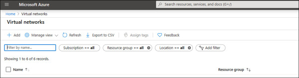
Figure 2-2 Azure Virtual Networks page
Click the Add button and the Create Virtual Network page appears, as shown in Figure 2-3.
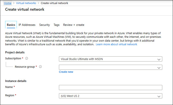
Figure 2-3 The Create Virtual Network page allows you to customize your VNet deployment
On the Basics tab, select the Subscription for the VNet and the Resource Group.
In the Name field, type a comprehensive name for the VNet, and in the Region field, select the Azure region in which the VNet is going to reside. Finally, click the IP Addresses tab.
On the IP Addresses page, in the IPv4 field, type the address space in classless inter-domain routing (CIRD) format; for example, you could enter 10.3.0.0/16.
Click the Add Subnet button. The Add Subnet blade appears, as shown in Figure 2-4.
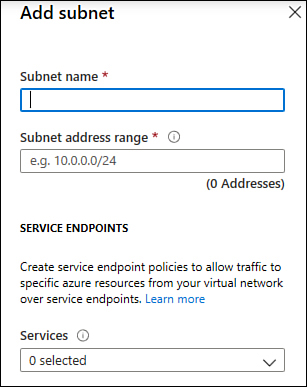
Figure 2-4 Add Subnet blade
In the Subnet Name field, type a name for this subnet.
In the Subnet Address Range, type the IP range for this subnet in CIDR format, such as 10.3.0.0/16. Keep in mind that the smallest supported IPv4 subnet is /29, and the largest is /8.
Click the Add button; the subnet that you just created appears under the Subnet Name section.
Leave the default selections for now and click the Review + Create button. The validation result appears, which is similar to the one shown in Figure 2-5.
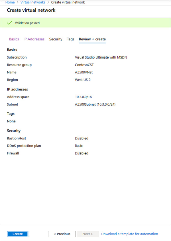
Figure 2-5 Summary of the selections with the validation results
Click the Create button.
The Overview page appears with the deployment final status. On this page, click the Go To Resource button and review these options on the left navigation pane: Overview, Address Space, and Subnets.
)
)
)
Notice that the parameters you configured during the creation of your VNet will be distributed among the different options on the VNet page. As you saw in the previous steps, creating a VNet using the Azure portal is a straightforward process, though in some circumstances, you might need to automate the creation process, and you can use PowerShell to do just that.
When you are creating your virtual network, you can use any IP range that is part of RFC 1918, which includes
224.0.0.0/4 (multicast)
255.255.255.255/32 (broadcast)
127.0.0.0/8 (loopback)
169.254.0.0/16 (link-local)
168.63.129.16/32 (internal DNS)
Also consider the following points:
Azure reserves x.x.x.0 as a network address and x.x.x.1 as a default gateway.
x.x.x.2 and x.x.x.3 are mapped to the Azure DNS IPs to the VNet space.
x.x.x.255 is reserved for a network broadcast address.
To automate that, you can either use PowerShell on your client workstation (using Connect-AzAccount to connect to your Azure subscription) or by using Cloud Shell directly from https://shell.azure.com. To create a virtual network using PowerShell, you need to use the New-AzVirtualNetwork cmdlet, as shown here:
$AZ500Subnet = New-AzVirtualNetworkSubnetConfig -Name AZ500Subnet -AddressPrefix
"10.3.0.0/24"
New-AzVirtualNetwork -Name AZ500VirtualNetwork -ResourceGroupName ContosoCST -Location
centralus -AddressPrefix "10.3.0.0/16" -Subnet $AZ500Subnet
In this example, you have the $AZ500Subnet variable, which configures a new subnet for this VNet using the New-AzVirtualNetworkSubnetConfig cmdlet. Next, the New-AzVirtualNetwork cmdlet is used to create the new VNet, and it calls the $AZ500Subnet variable at the end of the command line to create the subnet.
After creating your VNet, you can start connecting resources to it. In an IaaS scenario, it is very common to connect your virtual machines (VMs) to the VNet. Assuming you have Virtual Machine Contributor privileges in the subscription, you can quickly deploy a new VM the New-AzVM PowerShell cmdlet, as shown here:
New-AzVm `
    -ResourceGroupName "ContosoCST" `
    -Location "East US" `
    -VirtualNetworkName "AZ500VirtualNetwork" `
    -SubnetName "AZ500Subnet" `
    -Name "AZ500VM" `
Routing
In a physical network environment, you usually need to start configuring routes as soon as you expand your network to have multiple subnets. In Azure, the routing table is automatically created for each subnet within an Azure VNet. The default routes created by Azure and assigned to each subnet in a virtual network can’t be removed. The default route that is created contains an address prefix and the next hop (where the package should go). When traffic leaves the subnet, it goes to an IP address within the address prefix of a route; the route that contains the prefix is the route used by Azure.
When you create a VNet, Azure creates a route with an address prefix that corresponds to each address range that you defined within the address space of your VNet. If the VNet has multiple address ranges defined, Azure creates an individual route for each address range. You don’t need to worry about creating routes between subnets within the same VNet because Azure automatically routes traffic between subnets using the routes created for each address range. Also, differently from your physical network topology and routing mechanism, you don’t need to define gateways for Azure to route traffic between subnets. In an Azure routing table, this route appears as:
Source Default
Address prefix Unique to the virtual network
Next hop type Virtual network
If the destination of the traffic is the Internet, Azure leverages the system-default route 0.0.0.0/0 address prefix, which routes traffic for any address not specified by an address range within a virtual network to the Internet. The only exception to this rule is if the destination address is for one of Azure’s services. In this case, instead of routing the traffic to the Internet, Azure routes the traffic directly to the service over Azure’s backbone network. The other scenarios in which Azure will add routes are as follows:
When you create a VNet peering In this case, a route is added for each address range within the address space of each virtual network peering that you created.
When you add a Virtual Network Gateway In this case, one or more routes with a virtual network gateway listed as the next hop type are added.
When a VirtualNetworkServiceEndpoint is added When you enable a service endpoint to publish an Azure service to the Internet, the public IP addresses of the services are added to the route table by Azure.
You might also see None in the Next Hop Type column, in the routing table. Traffic routed to this hop is automatically dropped. Azure automatically creates default routes for 10.0.0.0/8, 192.168.0.0/16 (RFC 1918), and 100.64.0.0/10 (RFC 6598).
EXAM TIP
The exam might include scenarios that involve routing-related problems. Make sure to pay close attention to the details about the routing configuration and whether any routing configurations are missing.
At this point, you might ask: “If all these routes are created automatically, in which scenario should I create a custom route?” You should do this only when you need to alter the default routing behavior. For example, if you add an Azure Firewall or any other virtual appliance, you can change the default route (0.0.0.0/0) to point to this virtual appliance. This will enable the appliance to inspect the traffic and determine whether to forward or drop the traffic. Another example is when you want to ensure that traffic from hosts doesn’t go to the Internet; you can control the routing rules to accomplish that.
To create a custom route that is effective for your needs, you need to create a custom routing table, create a custom route, and associate the routing table to a subnet, as shown in the PowerShell sequence that follows.
Create the routing table using New-AzRouteTable cmdlet, as shown here:
$routeTableAZ500 = New-AzRouteTable `
  -Name 'AZ500RouteTable' `
  -ResourceGroupName ContosoCST `
  -location EastUS
Create the custom route using multiple cmdlets. First, you retrieve the route table information using Get-AzRouteTable, and then you create the route using Add-AzRouteConfig. Lastly, you use the Set-AzRouteTable to write the routing configuration to the route table:
Get-AzRouteTable `
  -ResourceGroupName "ContosoCST" `
  -Name "AZ500RouteTable" `
  | Add-AzRouteConfig `
  -Name "ToAZ500Subnet" `
  -AddressPrefix 10.0.1.0/24 `
  -NextHopType "MyVirtualAppliance" `
  -NextHopIpAddress 10.0.2.4 `
 | Set-AzRouteTable
Now that you have the routing table and the custom route, you can associate the route table with the subnet. Notice here that you first write the subnet configuration to the VNet using the Set-AzVirtualNetwork cmd. After that you use Set-AzVirtualNetworkSubnetConfig to associate the route table to the subnet:
$virtualNetwork | Set-AzVirtualNetwork
Set-AzVirtualNetworkSubnetConfig `
  -VirtualNetwork $virtualNetwork `
  -Name 'CustomAZ500Subnet' `
  -AddressPrefix 10.0.0.0/24 `
  -RouteTable $routeTableAZ500 | `
Set-AzVirtualNetwork
Virtual network peering
When you have multiple VNets in your Azure infrastructure, you can connect those VNets using VNet peering. You can use VNet peering to connect VNets within the same Azure region or across Azure regions; doing so is called global VNet peering.
When the VNets are on the same region, the network latency between VMs that are communicating through the VNet peering is the same as the latency within a single virtual network. It’s also important to mention that the traffic between VMs in peered virtual networks is not through a gateway or over the public Internet; instead, that traffic is routed directly through the Microsoft backbone infrastructure. To create a VNet peering using the Azure portal, follow these steps:
Navigate to the Azure portal at https://portal.azure.com.
In the search bar type virtual networks, and under Services, click Virtual Networks.
Click the VNet that you want to peer, and on the left navigation pane, click Peerings (see Figure 2-6).
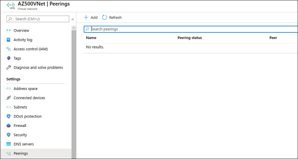
Figure 2-6 Configuring VNet peering
Click the Add button, and the Add Peering page appears, as shown in Figure 2-7.
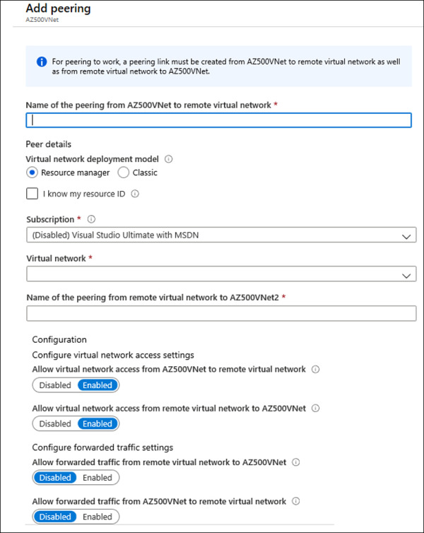
Figure 2-7 Adding a new peering
In the Name field, type a name for this peering.
In the Subscription field, select the subscription that has the VNet to which you want to connect.
In the Virtual Network field, click the drop-down menu and select the VNet that you want to peer.
In the Name Of The Peering From Remote Virtual Network field, type the name that you want this peering connection to appear on the other VNet.
The next two options—Allow Virtual Network Access From [VNet name] To Remote Virtual Network and Allow Virtual Network Access From Remote Virtual To [VNet name]—are used to control the communication between those VNets. If you want full connectivity from both directions, make sure to leave the Enabled option selected (default selection) for both. Enabling communication between virtual networks allows resources connected to either virtual network to communicate with each other with the same bandwidth and latency as if they were connected to the same virtual network.
The next two options—Allow Forwarded Traffic From Remote Virtual Network To [VNet name] and Allow Forwarded Traffic From [VNet name] To Remote Virtual Network—are related to allowing forwarded traffic. You should select Enable for both settings only when you need allow traffic that didn’t originate from the VNet to be forwarded by a network virtual appliance through a peering. For example, consider three virtual networks named VNetTX, VNetWA, and MainHub. A peering exists between each spoke VNet (VNetTX and VNetWA) and the Hub virtual network, but peerings don’t exist between the spoke VNets. A network virtual appliance is deployed in the Hub VNet, and user-defined routes can be applied to each spoke VNet to route the traffic between the subnets through the network virtual appliance. If this option is disabled, there will be no traffic flow between the two spokes through the hub.
Click OK to finish the configuration.
)
)
To configure a VNet peering using PowerShell, you just need to use the Add-AzVirtualNetworkPeering cmdlet, as shown here:
Add-AzVirtualNetworkPeering -Name 'NameOfTheVNetPeering' -VirtualNetwork SourceVNet
-RemoteVirtualNetworkId RemoteVNet
A peered VNet can have its own gateway, and the VNet can use its gateway to connect to an on-premises network. One common use of VNet peering is when you are building a hub-spoke network. In this type of topology, the hub is a VNet that acts as a central hub for connectivity to your on-premises network. The spokes are VNets that are peering with the hub, allowing them to be isolated, which increases their security boundaries. An example of this topology is shown in Figure 2-8.
)
Figure 2-8 Hub-spoke network topology using VNet peering
A hybrid network uses the hub-spoke architecture model to route traffic between Azure VNets and on-premises networks. When there is a site-to-site connection between the Azure VNet and the on-premises data center, you must define a gateway subnet in the Azure VNet. All the traffic from the on-premises data center would then flow via the gateway subnet.
Network address translation
Azure has a Virtual Network NAT (network address translation) capability that enables outbound-only Internet connectivity for virtual networks. This is a common scenario when you want that outbound connectivity to use a specified static public IP address (static NAT) or you want to use a pool of public IP addresses (Dynamic NAT).
Keep in mind that outbound connectivity is possible without the use of an Azure load balancer or a public IP address directly attached to the VM. Figure 2-9 shows an example of the topology with a NAT Gateway.
)
Figure 2-9 NAT Gateway topology
You can implement NAT by using a public IP prefix directly, or you can distribute the public IP addresses of the prefix across multiple NAT gateway resources. NAT also changes the network route because it takes precedence over other outbound scenarios, and it will replace the default Internet destination of a subnet. From an availability standpoint (which is critical for security), NAT always has multiple fault domains, which means it can sustain multiple failures without service outage.
To create a NAT Gateway for your subnet, you first need to create a public IP address and a public IP prefix. Follow the steps below to perform these tasks:
Navigate to the Azure portal at https://portal.azure.com.
In the main dashboard, click the Create A Resource button.
On the New page, type Public IP and click the Public IP Address option that appears in the list.
On the Public IP Address page, click the Create button; the Create Public IP Address page appears, as shown in Figure 2-10.
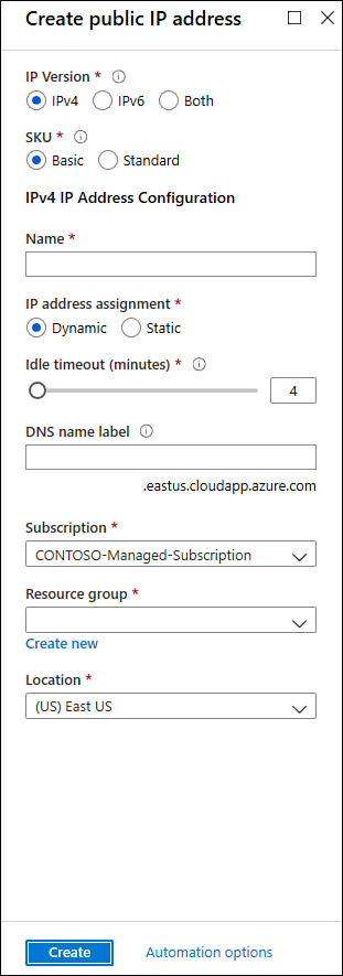
Figure 2-10 Creating a public IP address to be used by NAT Gateway
Type the name for this public IP address and select the subscription, resource group, and the Azure location. For this example, you can leave all other options with their default selections. Once you finish, click the Create button.
Now you should repeat steps 1 and 2. In the third step, type public IP prefix and click the Public IP Prefix option that appears in the drop-down menu.
On the Create A Public IP Prefix page, configure the following relevant options:
Select the appropriate Subscription.
Select the appropriate Resource Group.
Type the Prefix Name.
Select the appropriate Azure Region.
In the Prefix Size drop-down menu, select the appropriate size for your deployment.
Once you finish configuring these options, click the Review + Create button and click Create to finish.
Now that you have the two requirements fulfilled, you can create the NAT Gateway.
Navigate to the Azure portal at https://portal.azure.com.
In the main dashboard, click the Create A Resource button.
On the New page, type NAT Gateway and click the NAT Gateway option in the list.
On the NAT Gateway page, click Create. The Create Network Address Translation (NAT) Gateway page appears, as shown in Figure 2-11.
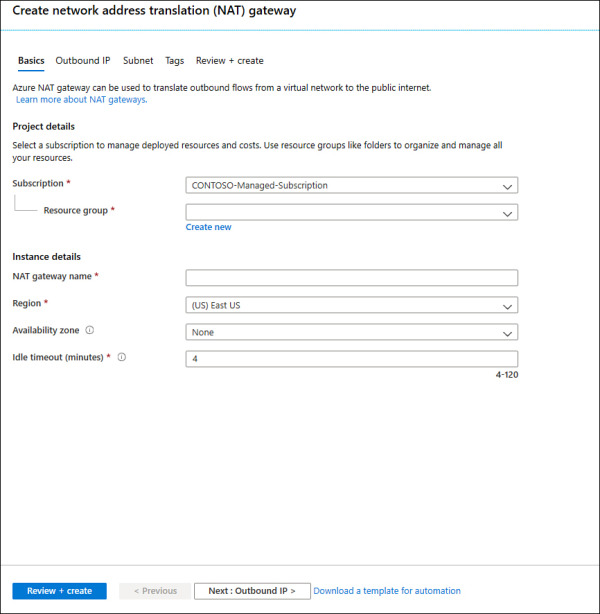
Figure 2-11 Creating a NAT Gateway in Azure
On the Basics tab, make sure to configure the following options:
Select the appropriate Subscription and Resource Group.
Type the NAT Gateway Name.
Select the appropriate Azure Region and Availability Zone.
Move to the next tab, Outbound IP, and select the Public IP Address and Prefix Name that you created previously.
Next, on the Subnet tab, you will configure which subnets of a VNet should use this NAT gateway.
The Tags tab is optional, and you should use it only when you need to logically organize your resources in a particular taxonomy to easily identify them later.
You can review a summary of the selections in the Review + Create tab. Once you finish reviewing it, click the Create button.
)
You can also use the New-AzNatGateway cmdlet to create a NAT Gateway using PowerShell, as shown:
New-AzNatGateway -ResourceGroupName "AZ500RG" -Name "nat_gt" -IdleTimeoutInMinutes 4
-Sku "Standard" -Location "eastus2" -PublicIpAddress PublicIPAddressName
Secure the connectivity of virtual networks
With organizations migrating to the cloud, virtual private networks (VPNs) are constantly used to establish a secure communication link between on-premises and cloud network infrastructure. While this is one common scenario, there are many other scenarios where a VPN can be used. You can use Azure VPN to connect two different Azure regions or different subscriptions.
Azure natively offers a service called VPN gateway, which is a specific type of virtual network gateway that is used to send encrypted traffic between an Azure virtual network and on-premises resources. You can also use a VPN gateway to send encrypted traffic between Azure virtual networks. When planning your VPN Gateway implementation, be aware that each virtual network can have only one VPN gateway, and you can create multiple connections to the same VPN gateway. Depending on the scenario, you can select from different types of VPN connectivity. The available options are
Site-to-Site (S2S) VPN This type of VPN is used in scenarios where you need to connect on-premises resources to Azure. The encrypted connection tunnel uses IPsec/IKE (IKEv1 or IKEv2).
Point-to-Site (P2S) VPN This type of VPN is used in scenarios where you need to connect to your Azure VNet from a remote location. For example, you would use P2S when you are working remotely (hotel, home, conference, and the like) and you need to access resources in your VNet. This VPN uses SSTP (Secure Socket Tunneling Protocol) or IKE v2 and does not require a VPN device.
VNet-to-VNet As the name states, this VPN is used in scenarios where you need to encrypt connectivity between VNets. This type of connection uses IPsec (IKE v1 and IKE v2).
Multi-Site VPN This type of VPN is used in scenarios where you need to expand your site-to-site configuration to allow multiple on-premises sites to access a virtual network.
ExpressRoute is another option that allows connectivity from your on-premises resources to Azure. This option uses a private connection to Azure from your WAN, instead of a VPN connection over the Internet.
VPN authentication
The Azure VPN connection is authenticated when the tunnel is created. Azure generates a pre-shared key (PSK), which is used for authentication. This pre-shared key is an ASCII string character no longer than 128 characters. This authentication happens for policy-based (static routing) or routing-based VPN (dynamic routing). You can view and update the pre-shared key for a connection with these PowerShell cmdlets:
Get-AzVirtualNetworkGatewayConnectionSharedKey This command is used to show the pre-shared key.
Set-AzVirtualNetworkGatewayConnectionSharedKey This command is used to change the pre-shared key to another value.
For point-to-site (P2S) VPN scenarios, you can use native Azure certificate authentication or Azure AD authentication. For native Azure certificate authentication, a client certificate is presented on the device, which is used to authenticate the users who are connecting. The certificate can be one that was issued by an enterprise certificate authority (CA), or it can be a self-signed root certificate. For native Azure AD, you can use the native Azure AD credentials. Keep in mind that native Azure AD is only supported for the OpenVPN protocol and Windows 10. (Windows 10 requires the use of the Azure VPN Client.)
If your scenario requires the enforcement of a second factor of authentication before access to the resource is granted, you can use Azure Multi-Factor Authentication (MFA) with conditional access. Even if you don’t want to implement MFA across your entire company, you can scope the MFA to be employed only for VPN users using conditional access capability.
Another option available for P2S is the authentication using RADIUS (which also supports IKEv2 and SSTP VPN). Keep in mind that RADIUS is only supported for VpnGw1, VpnGw2, and VpnGw3 SKUs. For more information about the latest VPN SKUs, visit http://aka.ms/az500vpnsku. Figure 2-12 shows an example of the options that appear when you are configuring a P2S VPN and you need to select the authentication type.
)
Figure 2-12 Authentication options for VPN
The options that appear right under the Authentication Type section will vary according to the Authentication Type you select. In Figure 2-12, Azure Certificate is chosen, and the page shows options to enter the Name and Public Certification Data for the Root Certificates and the Name and Thumbprint for the Revoked Certificates. If you select RADIUS authentication, you will need to specify the Server IP Address and the Server Secret. Lastly, if you select the Azure Active Directory option, you will need to specify the Tenant’s URL; the Audience (which identifies the recipient resource the token is intended for); and the Issuer (which identifies the Security Token Service (STS) that issued the token). Lastly, choose the Azure AD tenant.
Your particular scenario will dictate which option to use. For example, Contoso’s IT department needs to implement a VPN solution that can integrate with a certificate authentication infrastructure that it already has through RADIUS. In this case, you should use RADIUS certificate authentication. When using the RADIUS certificate authentication, the authentication request is forwarded to a RADIUS server, which handles the certificate validation. If the scenario requires that the certificate authentication be performed by the Azure VPN gateway, the right option would be to use the Azure native certificate authentication.
ExpressRoute encryption
If your connectivity scenario requires a higher level of reliability, faster speeds, consistent latencies, and higher security than typical connections over the Internet, you should use ExpressRoute, which provides layer 3 connectivity between your on-premises network and the Microsoft Cloud.
ExpressRoute supports two different encryption technologies to ensure the confidentiality and integrity of the data that is traversing from on-premises to Microsoft’s network. The options are
Point-to-point encryption by MACsec
End-to-end encryption by IPSec
MACsec encrypts the data at the media access control (MAC) level or at network layer 2. When you enable MACsec, all network control traffic is encrypted, which includes the border gateway protocol (BGP) data traffic, and your (customer) data traffic. This means that you can’t encrypt only some of your ExpressRoute circuits.
If you need to encrypt the physical links between your network devices and Microsoft’s network devices when you connect to Microsoft via ExpressRoute Direct, MACsec is preferred. MACsec also allows you to bring your own MACsec key for encryption and store it in Azure Key Vault. If this is the design choice, remember that you will need to decide when to rotate the key.
Keep in mind that when you update the MACsec key, the on-premises resources will temporally lose connectivity to Microsoft over ExpressRoute. This happens because MACsec configuration only supports pre-shared key mode, so you must update the key on both sides. In other words, if there is a mismatch, traffic flow won’t occur. Plan the correct maintenance window to reduce the impact on production environments.
The other option is to use end-to-end encryption with IPSec, which encrypts data at the Internet protocol (IP)–level or at network layer 3. A very common scenario is to use IPSec to encrypt the end-to-end connection between on-premises resources and your Azure VNet. In a scenario where you need to encrypt layer 2 and layer 3, you can enable MACsec and IPSec.
Point-to-site
To implement a point-to-site (P2S) VPN in Azure, you first need to decide what authentication method you will use based on the options that were presented earlier in this section. The authentication method will dictate how the P2S VPN will be configured. When configuring the P2S VPN, you will see the options available under Tunnel Type, as shown in Figure 2-13.
)
Figure 2-13 Different options for the VPN tunnel
Another important variable to select is the protocol that will be used. Use Table 2-1 to select the most-appropriate protocol based on the advantages and limitations:
Table 2-1 Advantages and limitations
Protocol |
Advantages |
Limitations |
OpenVPN Protocol |
This is a TLS VPN-based solution that can traverse most firewalls on the market. Can be used to connect from a variety of operating systems, including Android, iOS (versions 11.0 and above), Windows, Linux, and Mac devices (OSX versions 10.13 and above). |
Basic SKU is not supported. Not available for the classic deployment model. |
Secure Socket Tunneling Protocol (SSTP) |
Can traverse most firewalls because it uses TCP port 443. |
Only supported on Windows devices. Supports up to 128 concurrent connections, regardless of the gateway SKU. |
IKEv2 |
Standard-based IPsec VPN solution. Can be used to connect to Mac devices (OSX versions 10.11 and above). |
Basic SKU is not supported. Not available for the classic deployment model. Uses nonstandard UDP ports, so you need to ensure that these ports are not blocked on the user’s firewall. The ports in use are UDP 500 and 4500. |
EXAM TIP
For the AZ-500 exam, make sure to carefully read the scenarios because there will be indications of what the company wants to accomplish, and those indications will be used to decide which protocol to implement or which protocol is not an option for the specified scenario.
Site-to-site
A site-to-site (S2S) VPN is used in most scenarios to allow the communication from one location (on-premises) to another (Azure) over the Internet. To configure a S2S, you need the following prerequisites fulfilled before you start:
A VPN device on-premises that is compatible with Azure VPN policy-based configuration or route-based configuration. See the full list at https://aka.ms/az500s2sdevices.
Externally-facing public IPv4 address.
IP address range from your on-premises network that will be utilized to allow Azure to route to your on-premises location.
Configure network security groups and Application Security Groups
Network security groups (NSG) in Azure allow you to filter network traffic by creating rules that allow or deny inbound network traffic to or outbound network traffic from different types of resources. For example, you could configure an NSG to block inbound traffic from the Internet to a specific subnet that only allows traffic from a network virtual appliance (NVA).
Network security groups can be enabled on the subnet or to the network interface in the VM, as shown in Figure 2-14.
)
Figure 2-14 Different NSG implementations
In the diagram shown in Figure 2-14, you have two different uses of NSG. In the first case, the NSG is assigned to the subnet A. This can be a good way to secure the entire subnet with a single set of NSG rules. However, there will be scenarios where you might need to control the NSG on the network interface level, which is the case of the second scenario (subnet B), where VM 5 and VM 6 have a NSG assigned to the network interface.
When inbound traffic is coming through the VNet, Azure processes the NSG rules that are associated with the subnet first—if there are any—and then it processes the NSG rules that are associated with the network interface. When the traffic is leaving the VNet (outbound traffic), Azure processes the NSG rules that are associated with the network interface first, followed by the NSG rules that are associated to the subnet.
When you create an NSG, you need to configure a set of rules to harden the traffic. These rules use the following parameters:
Name The name of the rule.
Priority The order in which the rule will be processed. Lower numbers have high priority, which means that a rule priority 100 will be evaluated before rule priority 300. Once the traffic matches the rule, it will stop moving forward to evaluate other rules. When configuring the priority, you can assign a number between 100 and 4096.
Source Define the source IP, CIDR Block, Service Tag, or Application Security Group.
Destination Define the destination IP, CIDR Block, Service Tag, or Application Security Group.
Protocol Define the TCP/IP protocol that will be used, which can be set to TCP, UDP, ICMP, or Any.
Port Range Define the port range or a single port.
Action This determines the action that will be taken once this rule is processed. This can be set to Allow or Deny.
Before creating a new NSG and adding new rules, it is important to know that Azure automatically creates default rules on NSG deployments. Following is a list of the inbound rules that are created:
AllowVNetInBound
Priority 6500
Source VirtualNetwork
Source Ports 0-65535
Destination VirtualNetwork
Destination Ports 0-65535
Protocol Any
Access Allow
AllowAzureLoadBalancerInBound
Priority 6501
Source AzureLoadBalancer
Source Ports 0-65535
Destination 0.0.0.0/0
Destination Ports 0-65535
Protocol Any
Access Allow
DenyAllInbound
Priority 6501
Source AzureLoadBalancer
Source Ports 0-65535
Destination 0.0.0.0/0
Destination Ports 0-65535
Protocol Any
Access Deny
Below is a list of outbound rules that are created:
AllowVnetOutBound
Priority 6501
Source VirtualNetwork
Source Ports 0-65535
Destination VirtualNetwork
Destination Ports 0-65535
Protocol Any
Access Allow
AllowInternetOutBound
Priority 6501
Source 0.0.0.0/0
Source Ports 0-65535
Destination Internet
Destination Ports 0-65535
Protocol Any
Access Allow
DenyAllOutBound
Priority 6501
Source 0.0.0.0/0
Source Ports 0-65535
Destination 0.0.0.0/0
Destination Ports 0-65535
Protocol Any
Access Deny
Follow the steps below to create and configure an NSG, which in this example, will be associated with a subnet:
Navigate to the Azure portal by opening https://portal.azure.com.
In the search bar, type network security, and under Services, click Network Security Groups; the Network Security Groups page appears.
Click the Add button; the Create Network Security Group page appears, as shown in Figure 2-15.
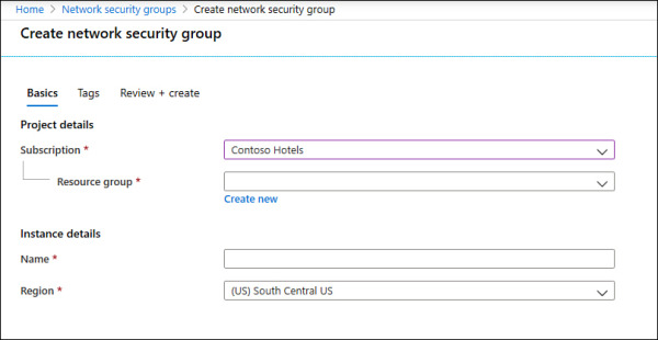
Figure 2-15 Initial parameters of the network security group
In the Subscription field, select the subscription where this NSG will reside.
In the Resource Group field, select the resource group in which this NSG will reside.
In the Name field, type the name for this NSG.
In the Region field, select the Azure region in which this NSG will reside.
Click Review + Create button, review the options, and click the Create button.
Once the deployment is complete, click the Go To Resource button. The NSG page appears.
)
At this point, you have successfully created your NSG, and you can see that the default rules are already part of it. The next step is to create the custom rules, which can be inbound or outbound. (This example uses inbound rules.) The same operation could be done using the New-AzNetworkSecurityGroup PowerShell cmdlet, as shown in the following example:
New-AzNetworkSecurityGroup -Name "AZ500NSG" -ResourceGroupName "AZ500RG" -Location
"westus"
Follow these steps to create an inbound rule that allows FTP traffic from any source to a specific server using Azure portal:
On the NSG page, under Settings in the left navigation pane, click Inbound Security Rules.
Click the Add button; the Add Inbound Security Rule blade appears, as shown in Figure 2-16.
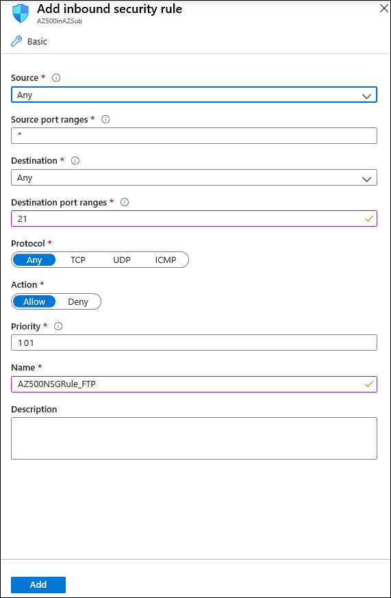
Figure 2-16 Creating an inbound security rule for your NSG
On this blade, you start by specifying the source, which can be an IP address, a service tag, or an ASG. If you leave the default option (Any), you are allowing any source. For this example, leave this set to Any.
In the Source Port Ranges field, you can harden the source port. You can specify a single port or an interval. For example, you can allow traffic from ports 50 to 100. Also, you can use comma to add another condition to the range, such as 50-100, 135, which specifies ports 50 through 100 and 135. Leave the default selection (*), which allows any source port.
In the Destination field, the options are nearly the same as the Source field. The only difference is that you can select the VNet as the destination. For this example, change this option to IP Addresses and enter the internal IP address of the VM that you created at the beginning of this chapter.
In the Destination Port Ranges field, specify the destination port that will be allowed. The default port is 8080; for this example, change it to 21.
In the Protocol field, you can select which protocol you are going to allow; in this case, change it to TCP.
Leave the Action field set to Allow, which is the default selection.
You can also change the Priority of this rule. Remember that the lowest priority is evaluated first. For this example, change it to 101.
In the Name field, change it to AZ500NSGRule_FTP and click the Add button.
The NSG will be created, and a new rule will be added to the inbound rules. At this point, your inbound rules should look like the rules shown in Figure 2-17.
)
Figure 2-17 List of inbound rules
While these are the steps to create the inbound rule, this NSG has no use if it is not associated with a subnet or a virtual network interface. For this example, you will associate this NSG to a subnet. The intent is to block all traffic to this subnet and only allow FTP traffic to this specific server. Use the following steps to create this association:
In the left navigation pane of the NSG Inbound Security Rules page under Settings, click Subnets.
Click the Associate button, and in the Virtual Network drop-down menu, select the VNet where the subnet resides.
After this selection, you will see that the Subnet drop-down menu appears; select the subnet and click the OK button.
You could also use PowerShell to create an NSG and then associate the NSG to a subnet. To create an NSG using PowerShell, use the New-AzNetworkSecurityRuleConfig cmdlet, as shown in the following example:
$MyRule1 = New-AzNetworkSecurityRuleConfig -Name ftp-rule -Description "Allow FTP"
-Access Allow -Protocol Tcp -Direction Inbound -Priority 100 -SourceAddressPrefix *
-SourcePortRange * -DestinationAddressPrefix * -DestinationPortRange 21
Application security group
If you need to define to define granular network security policies based on workloads that are centralized on application patterns instead of explicit IP addresses, you need to use the application security group (ASG). An ASG allows you to group VMs and secure applications by filtering traffic from trusted segments of your network, which adds an extra level of micro-segmentation.
You can deploy multiple applications within the same subnet and isolate traffic based on ASGs. Another advantage is that you can reduce the number of NSGs in your subscription. For example, in some scenarios, you can use a single NSG for multiple subnets of your virtual network and perform the micro-segmentation on the application level by using ASG. Figure 2-18 shows an example of how ASG can be used in conjunction with NSG.
)
Figure 2-18 ASG used as the destination in the NSG routing table
In the example shown in Figure 2-18, two ASGs have been created to define the application pattern for a web application and another ASG to define the application pattern for a SQL database. Two VMs are part of each group, and the ASG is used in the routing table of the NSG located in subnet A. In the NSG routing table, you can specify one ASG as the source and destination, but you cannot specify multiple ASGs in the source or destination.
When you deploy VMs, you can make them members of the appropriate ASGs. In case your VM has multiple workloads (Web App and SQL, for example), you can assign multiple ASGs to each application. This will allow you to have different types of access to the same VM according to the workload. This approach also helps to implement a zero-trust model by limiting access to the application flows that are explicitly permitted. Follow these steps to create an ASG:
Navigate to the Azure portal at https://portal.azure.com.
In the search bar, type application security and under Services, click Application Security Groups.
In the Application Security Groups dashboard, click the Add button, which makes the Create An Application Security Group page appear, as shown in Figure 2-19.
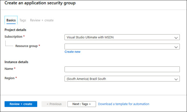
Figure 2-19 Create An Application Security Group
In the Subscription drop-down menu, select the appropriate subscription for this ASG.
In the Resource Group drop-down menu, select the resource group in which this ASG will reside.
In the Name field, type a name for this ASG.
In the Region drop-down menu, select the appropriate region for this ASG and click the Review + Create button.
On the Review + Create button page, click the Create button.
)
Now that the ASG is created, you need to associate this ASG to the network interface of the VM that has the workload you want to control. Follow these steps to perform this association:
Navigate to the Azure portal at https://portal.azure.com.
In the search bar, type virtual and under Services, click Virtual Machines.
Click in the VM that you want to perform this association.
On the VM’s page, in the Settings section, click the Networking option.
Click the Application Security Group tab, and the page shown in Figure 2-20 appears.
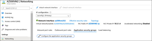
Figure 2-20 Associating the ASG to the virtual network interface card
Click the Configure The Application Security Groups button and the Configure The Application Security Groups blade appears, as shown in Figure 2-21.
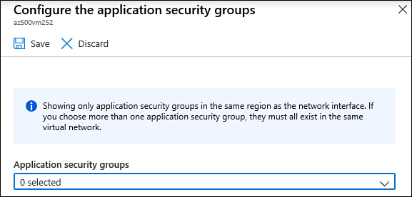
Figure 2-21 Selecting the ASG
Select the appropriate ASG and click the Save button.
)
)
)
)
)
You can also use the New-AzApplicationSecurityGroup cmdlet to create a new ASG, as shown in the following example:
New-AzApplicationSecurityGroup -ResourceGroupName "MyRG" -Name "MyASG" -Location "West
US"
Now when you create your new NSG rule for inbound or outbound traffic, you can select the ASG as source or destination.