Implement Datacenter Compute Solutions with Virtual Machine Manager (VMM)
- By Jeff Graves and Joel Stidley
- 1/23/2018
In Skill 2.2 from Exam Ref 70-745 Implementing a Software-Defined DataCenter, learn how to define and document fabric resource endpoints, implement SDN using VMM Service Templates, configure single tenant and multi-tenant scenarios, and more.
Skill 2.2 Plan for and implement SDN solution
Software-Defined Networking (SDN) allows for policy-based, centralized configuration and management of physical and virtual switching and routing infrastructure at scale. In System Center and Windows Server 2016 it consists of separate management, control, and data planes that are abstracted and managed by Virtual Machine Manager. SDN in Windows Server 2016 has several key components:
Physical Infrastructure These include the physical switches in the environment that connect to the virtualization hosts as well as physical routers and other network devices that can be managed by VMM.
Virtual Switches The extension Hyper-V virtual switch that connects virtual machines and virtual network functions to the physical network.
Switch Embedded Teaming (SET) A new solution in Windows Server 2016 that integrates functionality of teaming into the virtual switch. SET is required to use the HNV v2 SDN solution in Windows Server 2016.
Network Controller New in Windows Server 2016, the Network Controller is a highly available, scalable server role that provides a centralized interface for configuring, managing, and monitoring physical and virtual network infrastructure. The Network Controller has both a northbound API enabling you to communicate with the Network Controller, and a southbound API that enables the Network Controller to communicate with other network devices.
Network Virtualization The heart of SDN relies on network virtualization enabling a scalable network architecture to be overlaid on physical infrastructure. Hyper-V Network Virtualization (HNV) enables tenant isolation on a shared network fabric supporting VLANs, NVGRE, and VXLAN encapsulation.
HNV v1 Network Virtualization was first introduced in Windows Server 2012 and relies on WMI through VMM to map customer addresses to physical addresses. NVGRE is the only encapsulation protocol supported.
HNV v2 New in Windows Server 2016 is a HNV stack based on the Azure Virtual Filtering Platform (VFP) forwarding extension. This enables a much more scalable and programmable architecture including NFV components. Multiple encapsulation protocols are supported with VXLAN being the default.
Network Function Virtualization (NFV) The network consists of more than just hosts, and so does the SDN. Traditional network functions that are performed by hardware devices are virtualized in SDN:
Datacenter Firewall HNV provides a distributed firewall with 5-tuple Access Control Lists (ACLs) that can be applied at the virtual machine or subnet level.
Internal DNS Service for SDN (iDNS) Guest workloads rely on DNS to communicate. iDNS provides tenant name resolution services.
Software Load Balancing for SDN (SLB) Distributing traffic among virtual machines is supported via a SLB that provides L4 north-south and east-west TCP/UDP load balancing for both public and private addresses. SLB is compatible with HNV and provides endpoint monitoring capabilities.
Remote Access Service Gateway for SDN (RAS) The scalable, multi-tenant RAS gateway enables external connectivity for HNV workloads and provides S2S VPN, P2S VPN, GRE tunneling, and BGP routing capabilities.
Plan for Software-Defined Network infrastructure
The SDN fabric infrastructure runs as virtual machines on Windows Server 2016 Hyper-V hosts in the environment. The Network Controller runs as a scale-out Service Fabric Application across at least three nodes with one primary node and two replica nodes. The Network Controller manages additional SDN fabric infrastructure components such as SLB and RAS Gateways, which can also be scaled out. Table 2-5 lists the minimum requirements for the VMs hosting these roles.
 EXAM TIP
The SDN roles must be installed on virtual machines hosted on the Hyper-V hosts for which they are providing services. It is not supported to install these roles on physical hardware.
TABLE 2-5 Minimum requirements for infrastructure VMs
Role |
Nodes |
CPU |
RAM |
Disk |
Network Controller |
3 |
4 |
4GB |
75GB |
SLB |
3 |
8 |
8GB |
75GB |
RAS |
3 |
8 |
8GB |
75GB |
Properly planning for your Software-Defined Networking topology is crucial in ensuring proper operation and scalability of the network. The SDN components in Windows Server and System Center 2016 rely on several logical network definitions and subnets for intercommunication. Figure 2-15 illustrates how the SDN roles communicate on these logical networks.
Management Network Communication between SDN fabric roles, Hyper-V hosts, and VMM occurs on the Management Network. This network should be routable and created as its own VMM Logical Network using no isolation.
HNV Provider Network This underlay network is used for the provider address space of Hyper-V Network Virtualization for overlay tenant virtual networks. This network should be routable and the VMM Logical Network should be created using no isolation, and managed by the network controller.
Transit Network SLB and RAS Gateways use this network for BGP peering and to route external tenant traffic. This network should be routable and created as its own VMM Logical Network using no isolation and managed by the Network Controller.
PublicVIP This network contains publicly routable front-end VIP addresses used to access tenant resources. This network should be created as its own VMM Logical Network using no isolation and managed by the Network Controller.
PrivateVIP This network contains non-routable VIP addresses used by tenant resources. This network is not routable and should be created as its own VMM Logical Network and managed by the Network Controller.
GREVIP This network contains publicly routable VIP endpoint address assigned to RAS Gateways for S2S GRE tunnels. This network should be created as its own VMM Logical Network using no isolation and managed by the Network Controller.
Storage At least two non-routable storage networks for RDMA NICs should be created on separate VLANs. These VMM Logical Networks can be created using VLAN isolation.
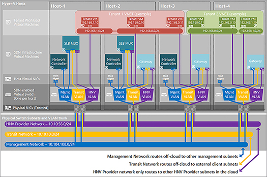
FIGURE 2-15 Diagram showing Logical Networking configuration for SDN
BGP peering on the Transit network is used to advertise routing information for the VIP subnets used by the SLB and RAS Gateways. The Public, Private, and GRE VIP networks should be externally routable to the BGP peer, typically a managed router or Windows Server with RRAS.
Define and document fabric resource endpoints such as host servers, logical networks, SLB multiplexers, VLANs, and service credentials
The SDN fabric infrastructure in VMM is deployed using service templates, so gathering information about the deployment ahead of time helps to ensure the proper configuration of SDN. You need to configure and gather the following to set up SDN:
Virtual Hard Disk A sysprepped virtual hard disk containing Windows Server 2016 is needed to deploy SDN. Ensure the VHD/VHDX is fully patched and generalized.
Host Servers Hyper-V host servers must be running Windows Server 2016 and should be configured with a management adapter that can communicate with VMM. Hosts that will be managed by SDN should be in a dedicated VMM host group.
Logical Networks Configure appropriate VLANs and subnets to support SDN per Table 2-6. The management Logical Network, Network Site, IP Pool, and VM Network will need to be created in VMM prior to deploying the SDN service templates. Logical Networks managed by the Network Controller cannot be created until after the service template is successfully deployed.
TABLE 2-6 Logical Networks for SDN
Name |
Network |
VLAN |
Gateway |
NC |
DIP Pool |
VIP Pool |
Management |
10.184.108.0/24* |
7 |
10.184.108.1 |
10.184.108.4-10.184.108.254 |
||
HNV Provider |
10.10.56.0/23* |
11 |
10.10.56.1 |
x |
10.10.56.4-10.10.56.254 |
|
Transit |
10.10.10.0/24* |
10 |
10.10.10.1 |
x |
10.10.10.4-10.10.10.254 |
|
Private VIP |
20.20.20.0/27** |
20.20.20.1 |
x |
20.20.20.4-20.20.20.30 |
||
GRE VIP |
31.30.30.0/24** |
31.30.30.1 |
x |
31.30.30.4-31.30.30.254 |
||
Public VIP |
41.40.40.0/27** |
41.40.40.1 |
x |
41.40.40.4-41.40.40.30 |
||
Storage1 |
10.60.36.0/25* |
8 |
10.60.36.4-10.40.1.126 |
|||
Storage2 |
10.60.36.128/25* |
9 |
10.60.36.131-10.60.36.254 |
BGP The SLB and RAS Gateway VMs need to be assigned unique private ASNs (64512-65535) and the BGP peer should be configured to receive route definitions from the SDN VMs.
Service Credentials VMM uses Kerberos authentication to communicate with the network controller, SLB and RAS Gateway VMs. Create two service accounts in VMM: one to deploy the network controller infrastructure, and one that will be used by VMM to communicate with the Network Controller. You will also need to create separate Network Controller Admins and Clients Active Directory domain local groups. The Network Controller Admins group the VMM service account to deploy the Network Controller infrastructure. The Network Controller Clients group should contain the service account that the VMM will use to communicate with the network controller after deployment. Users in these groups must also be members of the Domain Users group. You will also need to create a VMM Service Account for the local administrator on the SDN VMs.
Certificates The Network Controller deployment also requires the use of certificates, either self-signed or from a certificate authority. The certificate must include the Server Authentication EKU (OID 1.3.6.1.5.5.7.3.1) with a Subject Name that matches the DNS name of the network controller for single node deployments, or the DNS cluster name for scale-out deployments. You need to export the certificate in PFX format including the private key protected by a password. Additionally, you need the trusted root CA certificate or self-signed certificate in Base64 CER format.
Diagnostic Log Share SDN can centrally log diagnostic information to an SMB share. You need at least 75GB of free space on the share. You also need a domain username and password with modify permissions to the share.
REST Endpoint A FQDN for the REST Endpoint of the Network Controller service is used for communication from VMM. For a single node deployment, this should be the FQDN of the network controller node. For a multi-node deployment, this should be the FQDN you want to use for the cluster. For example: nccluster.contoso.int. Do not pre-create the A record for the rest endpoint because this can interfere with the Network Controller deployment.
Implement SDN using VMM Service Templates
Deploying SDN in VMM is done using Service Templates available on GitHub. The SDN / VMM folder contains all the resources and scripts needed to deploy SDN using VMM. Table 2-7 lists the components and their purpose.
TABLE 2-7 SDN resources and scripts from GitHub
Path |
Name |
Type |
Description |
Templates / GW |
EdgeServiceTemplate _Generation1.xml |
Service Template |
Service Template for production deployment of RAS Gateway role using Gen1 VM. |
Templates / GW |
EdgeServiceTemplate _Generation2.xml |
Service Template |
Service Template for production deployment of RAS Gateway role using Gen2 VM. |
Templates / NC |
EdgeDeployment.cr |
VMM Custom Resource |
VMM Library resource containing scripts used for installing SLB and RAS Gateway roles |
Templates / NC |
NCCertificate.cr |
VMM Custom Resource |
VMM Library resource containing Base64 CER format of Network Controller certificate |
Templates / NC |
NCSetup.cr |
VMM Custom Resource |
VMM Library resource containing scripts used for installing Network Controller. |
Templates / NC |
ServerCertificate.cr |
VMM Custom Resource |
VMM Library resource containing PFX format of Network Controller certificate |
Templates / NC |
TrustedRootCertificate.cr |
VMM Custom Resource |
VMM Library resource containing Base64 CER format of self-signed network controller certificate or Root CA |
Templates / NC |
Network Controller Production Generation 1 VM.xml |
Service Template |
Service Template for 3-node production deployment of network controller using Gen1 VM. |
Templates / NC |
Network Controller Production Generation 2 VM.xml |
Service Template |
Service Template for 3-node production deployment of network controller using Gen2 VM. |
Templates / NC |
Network Controller Standalone Generation 1 VM.xml |
Service Template |
Service Template for single-node test deployment of network controller using Gen1 VM. |
Templates / NC |
Network Controller Standalone Generation 2 VM.xml |
Service Template |
Service Template for single-node test deployment of network controller using Gen2 VM. |
Templates / SLB |
SLB Production Generation 1 VM.xml |
Service Template |
Service Template for production deployment of SLB MUX role using Gen1 VM. |
Templates / SLB |
SLB Production Generation 2 VM.xml |
Service Template |
Service Template for production deployment of SLB MUX role using Gen2 VM. |
Follow these steps to implement SDN using VMM service templates:
Download the scripts for GitHub: https://github.com/Microsoft/SDN.
Copy the VMM Custom Resources from the SDN / VMM / Templates / NC folder to an appropriate location in the VMM library (see Figure 2-16). Refresh the library share.
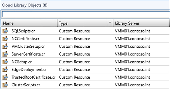
FIGURE 2-16 Imported SDN resources in the VMM library
Put the PFX certificate for the Network Controller into the ServerCertificate.cr folder (see Figure 2-17), the Base64 CER format certificate of the network controller into the NCCertificate.cr folder, and if necessary, place the trusted root certificate or a copy of the self-signed certificate in Base64 CER format into the TrustedRootCertificate.cr folder.
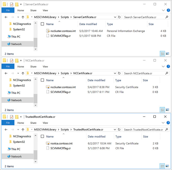
FIGURE 2-17 Certificate resources in the appropriate resource folders
Import the appropriate Network Controller template that matches the generation of the VHD/VHDX that has been prepared. When importing the service template, map the resources to the VMM Library objects in your environment.
A. In the VMM console, click Library > Templates > Service Templates. Click Import > Import Template from the ribbon.
B. Click Browse, and select the XML service template. Click Next.
C. Name the Service Template and set a Release. Map each of the resources to library objects using the Edit icon, as shown in Figure 2-18. Click Next.
D. Confirm the settings on the Summary page, and click Finish to import the Service Template.
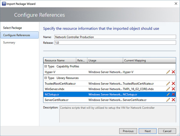
FIGURE 2-18 Configure references when importing a service template into the VMM library
It may be necessary to customize the service template for your environment.
Product Key Enter the appropriate product key for the prepared VHD/VHDX image or use AVMA keys.
Availability If deploying to a Hyper-V cluster, modify the VM hardware configuration to make the VM highly available.
IP Address By default, an IP will be assigned from the defined IP address pool associated with the selected Management VM Network during deployment. If using DHCP, set the IPv4 Address Type on the service template to Dynamic.
Storage Associate the operating system disk for the VM with the appropriate storage classification for the host group or cloud where the network controller will be deployed.
Nodes The service template defaults to a minimum and maximum of three nodes. You can increase the maximum node count as necessary for your environment. For production deployments, a minimum of three nodes is required.
)
)
You can modify service template machine tier settings by opening the service template in Designer mode.
In the VMM console, click Library > Templates > Service Templates. Right-click the service template and select Open In Designer.
Right-click the Machine Tier VM, and select Properties.
Modify settings for the machine tier. Click OK when finished.
Click Save, and Validate to save the service template (see Figure 2-19).
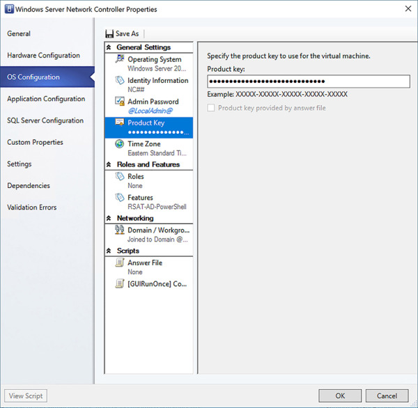
FIGURE 2-19 Configuring settings for Machine Tier in service template
Next, you will configure a deployment of the network controller. Table 2-8 lists the parameters and their purpose.
TABLE 2-8 Network Controller service template parameters
Setting
Description
ClientSecurityGroup*
This is the Network Controller Clients AD group you created earlier in DOMAIN\Group format.
DiagnosticLogShare
This the SMB share for diagnostic logs in \\FQDN\Share format.
DiagnosticLogSharePassword
This is the password for the user with modify permissions to the SMB share.
DiagnositicLogShareUsername
This is the username for of the user with modify permissions to the SMB share in DOMAIN\User format.
LocalAdmin*
This is the VMM RunAs account for the local Administrator on the VMs.
Management*
This is the Management VM Network the VMs will connect to.
MgmtDomainAccount*
This is the VMM RunAs account of the service account that will deploy the network controller.
MgmtDomainAccountName*
This is the username of the RunAs account mapped to MgmtDomainAccount in DOMAIN\User format. This user will be added to the local Administrators group on each node.
MgmtDomainAccountPassword*
This is the password of the RunAs account mapped to MgmtDomainAccount.
MgmtDomainFQDN*
This is the FQDN of the AD domain that VMs will join.
MgmtSecurityGroup*
This is the Network Controller Admins AD group you created earlier in DOMAIN\Group format.
RestEndPoint*
This is the FQDN of the REST Endpoint of the Network Controller. For example: nccluster.contoso.int.
ServerCertificatePassword*
This is the password for the private key of the network controller certificate in PFX format.
In the VMM console, click Library > Templates > Service Templates. Right-click the service template and select Configure Deployment.
Enter a name for the VMM service (for example: NCCluster), select the host group or cloud destination and the Management VM Network the Network Controller nodes will use (see Figure 2-20). Click OK.
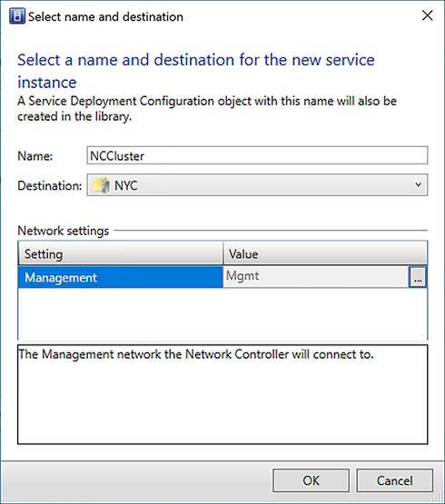
FIGURE 2-20 Create a deployment for Network Controller service template
Populate the Service Template Settings. Click Refresh Preview to place the VMs. Click Deploy Service when ready (see Figure 2-21).
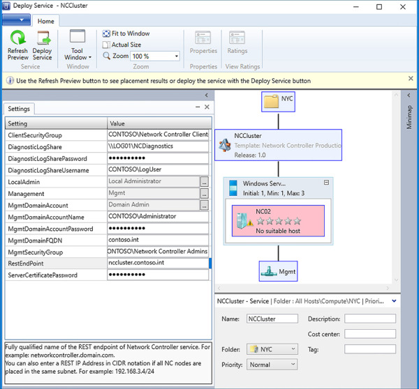
FIGURE 2-21 Configure deployment for Network Controller service template
Monitor the VMM Job to ensure successful deployment of the Network Controller.
Once the Network Controller deployment has completed, you will add it as a network service in VMM using the service account you created previously.
In the VMM console, click Fabric > Networking > Network Service. Right-click and select Add Network Service (see Figure 2-22). Click Next.
Enter a name and description for the network service. Click Next.
Select the Manufacturer (Microsoft) and Model (Microsoft Network Controller) for the network service. Click Next.
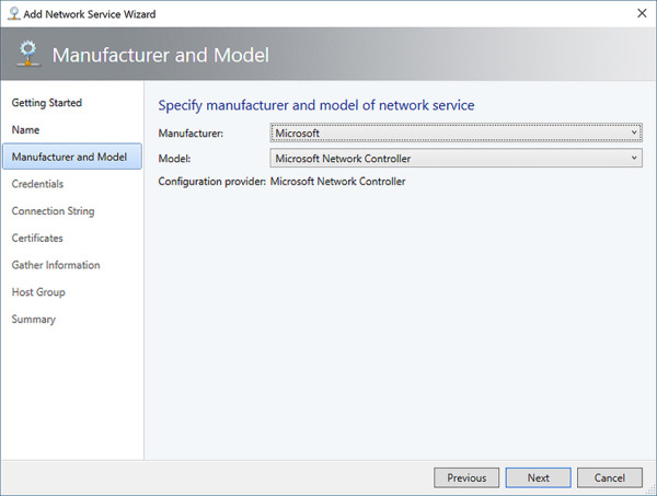
FIGURE 2-22 Specify manufacturer and model of network service in VMM
Set the Run As account to the MgmtDomainAccount you specified in the service template deployment settings. Click Next.
The connection string (see Figure 2-23) should specify the REST Endpoint and VMM Service name (for example: serverURL=https://nccluster.contoso.int/;servicename=NCCluster). Click Next.
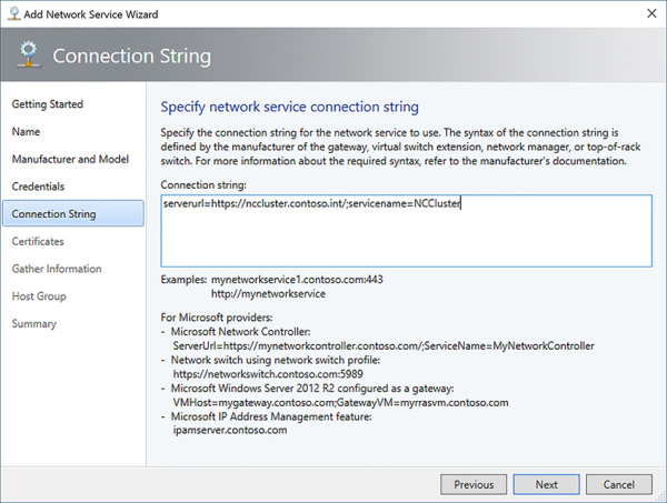
FIGURE 2-23 Specify connection string for the Network Controller in VMM
Confirm the type of certificate that was deployed with the Network Controller. Check the appropriate box to confirm the certificates can be imported to the trusted root store on the VMM server (see Figure 2-24). Click Next.
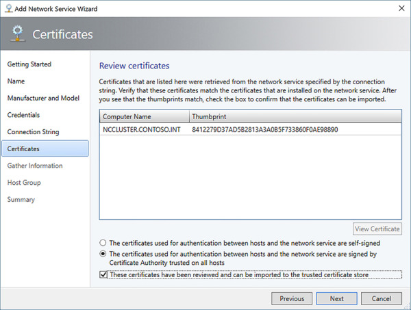
FIGURE 2-24 Review certificates for the Network Controller in VMM
Click Scan Provider to discover information about the Network Controller (see Figure 2-25). Click Next.
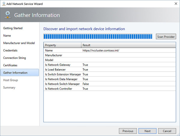
FIGURE 2-25 Discover Network Controller properties
Specify the Host Group that the Network Controller will service (see Figure 2-26). Click Next.
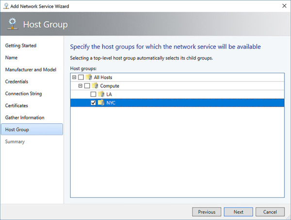
FIGURE 2-26 Specify the host groups that the Network Controller will manage
Confirm the settings on the Summary page, and click Finish to create the Network Controller Network Service.
The Network Controller will install the Network Controller host agent service on each of the Hyper-V hosts in the host groups managed by the Network Controller. Additionally, the Network Controller will take over management of logical switches on the Hyper-V hosts. Once the job is complete, you can configure the fabric resources.
Create the HNV Provider, Transit, Private VIP, GRE VIP, and Public VIP logical networks and IP pools as defined in Table 2-6. Ensure that the Managed By Microsoft Network Controller check box is selected (see Figure 2-27).
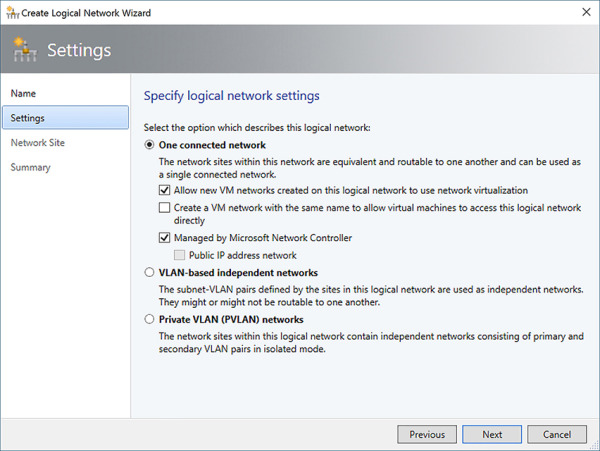
FIGURE 2-27 Specify Logical Network settings when creating a logical network
Modify the Uplink Port Profile that is assigned to a logical switch to add the logical networks to the switch (see Figure 2-28).
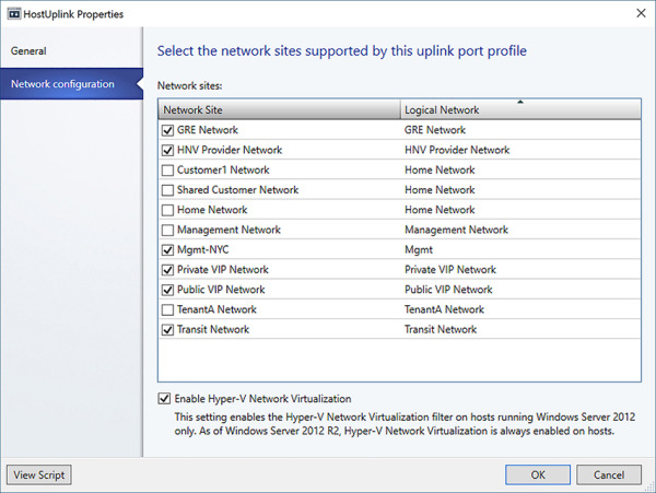
FIGURE 2-28 Add logical networks to uplink port profile
)
)
)
)
)
)
)
)
)
You can now create tenant VM networks using network virtualization on the HNV provider network.
Configure single tenant and multi-tenant scenarios
VMM supports both single tenant and multi-tenant networking scenarios using various methods of isolation including VLAN, PVLAN, and network virtualization. The specific networking topology and configuration depends on your network capabilities and desired isolation.
Network Virtualization This is the highly scalable Software-Defined Networking technology that enables service providers to host multiple tenant networks on a single provider network. Tenant customer addresses are translated to provider addresses when communicating on the physical network, enabling tenants to bring their own IP addresses and reduce VLAN usage on the physical network. Multiple VM networks can be created on a provider logical network.
VLAN This is the traditional layer 2 network segmentation using 802.1Q tagging of traffic to the physical network layer. One VM network can be associated for each VLAN in the logical network.
PVLAN Private VLANs are a type of layer 2 network segmentation that prohibits east-west traffic between hosts on the VLAN enabling them to communicate only with uplink ports. One VM network can be associated for each PVLAN in the logical network.
No isolation VMM also supports scenarios where no network isolation is enabled. A single VM network can be associated to a logical network with no isolation.
Create a virtual network in VMM:
In the VMM console, click VMs And Services > VM Networks. Right-click and select Create VM Network.
Give the Virtual Network a name and description. Select the logical network to associate with the VM network. To create a HNV overlay network, select the HNV Provider logical network (see Figure 2-29). Click Next.
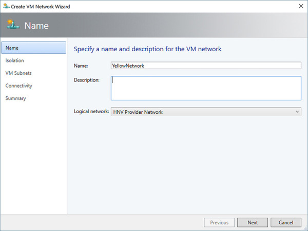
FIGURE 2-29 Create an HNV overlay virtual network in VMM
Select the type of isolation for the VM network (see Figure 2-30). Click Next.
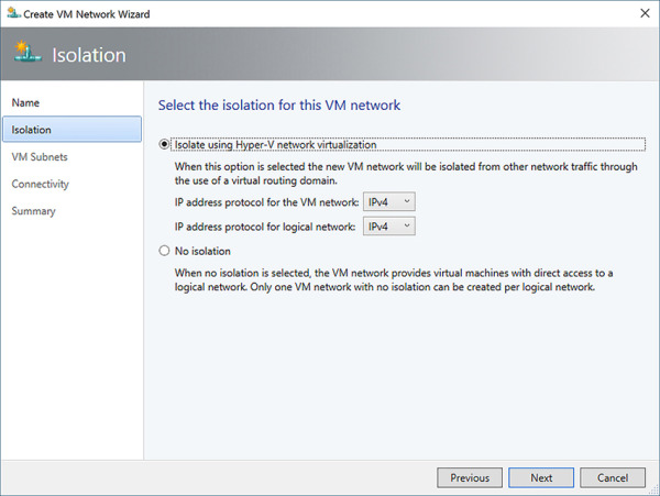
FIGURE 2-30 Configure VM network isolation settings
Click Add to add a VM subnet (see Figure 2-31). Specify a name and the CIDR notation of the subnet. Click Next.
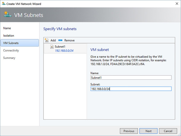
FIGURE 2-31 Add a subnet to the VM Network
You can configure connectivity settings for the virtual network including VPN connections and NAT. We will investigate these settings more in skills 2.4 and 2.5. Click Next.
Confirm the settings on the Summary page, and click Finish to create the VM network.
)
)
)
Define front-end Virtual IPs (VIPs) and back-end Dynamic IPs (DIPs) in multi-tier scenarios
Software-Defined Networking in VMM supports the use of Virtual IPs to be used with the SLB MUX for load balancing and NAT of private-to-public traffic. Virtual IPs (VIPs) are addresses assigned to the MUX that translate to Dynamic IPs (DIPs) that are assigned to hosts. These VIP addresses can either be externally available (north-south) to resources outside of the cloud environment, including the Internet, for services like web servers, or internally available (east-west) to other hosts in the cloud environment for services like database clusters. VIPs and DIPs are defined when creating an IP pool for a logical network by defining the start and ending IP address ranges and the range of IPs reserved for VIP (see Figure 2-32). Routes for VIPs are published outside of the cloud environment using BGP.
)
FIGURE 2-32 Define IP address range (DIPs) and VIPs in a static IP pool
EXAM TIP
Do not use the first three addresses in the subnet when configuring a static IP pool’s address range.
Install and configure the SDN Host Agent
Once a logical network managed by the Network Controller is assigned to a logical switch and uplink port profile of a Hyper-V host, VMM deploys the Network Controller Host Agent service to the Hyper-V hosts associated with the logical switch. The Host Agent is responsible for receiving policy configuration and updates from the Network Controller cluster, which is then used to configure routing and ACLs on the local Hyper-V switch. Check the status of the Hyper-V host to ensure the Network Controller Host Agent is installed and communicating with VMM as in Figure 2-33.
Exam Tip
The agent is supported on all versions of Windows Server 2016 that support Hyper-V, including Nano Server.
)
FIGURE 2-33 Confirm Network Controller Host Agent status on Hyper-V host
Configure DNS integration with SDN including iDNS
DNS is a critical component of the networking topology that enables workloads to communicate within their own networks and externally. The use of network virtualization can present problems for shared resources given the possibility of overlapping IP subnets and isolated tenant environments. To overcome this, Internal DNS Service (iDNS) can provide name resolution for tenant workloads on isolated networks. The iDNS proxy service runs on each Hyper-V host that can forward DNS traffic from tenant networks to Active Directory Integrated DNS servers in the host fabric. The network controller manages registration of iDNS servers and zone to be used for storing of VM host records while also configuring the iDNS proxy with required settings for tenant name resolution. Host names for tenant VMs are stored as DNS Resource Records under the zone configured for iDNS in the format <VM Name>.<VN DNS Suffix>.<iDNS Zone>:
VM Name The name of the tenant VM
VN DNS Suffix The DNS suffix of the tenant virtual network
iDNS Zone The zone configured for iDNS (for example: contoso.int)
iDNS is not integrated with VMM, therefore you must configure iDNS manually using PowerShell. Use the SDN Express scripts on GitHub to issue calls directly to the network controller REST endpoint. Follow these steps to configure iDNS:
Deploy at least two AD Integrated DNS VMs in a perimeter network. Ensure that the Hyper-V hosts and Network Controller nodes can communicate with the IP addresses assigned to the DNS VMs.
Create a new network credential with permissions to manage the DNS servers:
$credential = New-Object Microsoft.Windows.Networkcontroller.credentialproperties
$credential.type = “usernamePassword”
$credential.username = “Contoso\DNSAdmin”
$credential.password = “<Plain Text Password>”
New-NetworkControllerCredential -ConnectionUri $uri -Properties $credential -
ResourceId “iDnsServer-Credential”
Create a web request with the iDNS configuration including IP addresses of iDNS servers and credential with permissions to manage the DNS servers:
$request = @{}
$request.properties = @{}
$request.properties.zone = “contoso.int”
$request.properties.connections = @()
$connection1 = @{}
$connection1.managementAddressses = @(“10.184.108.9”)
$connection1.credential = @{“resourceRef”=”/credentials/iDnsServer-Credential”}
$connection1.credentialType = “usernamePassword”
$request.properties.connections += $connection1
$connection2 = @{}
$connection2.managementAddressses = @(“10.184.108.10”)
$connection2.credential = @{“resourceRef”=”/credentials/iDnsServer-Credential”}
$connection2.credentialType = “usernamePassword”
$request.properties.connections += $connection2
$body = ConvertTo-Json $request -Depth 100
Invoke-WebRequest -Headers @{“Accept”=”application/json”} -ContentType
“application/json; charset=UTF-8” -Method “Put” -Uri
“$uri/Networking/v1/iDnsServer/configuration” -Body $body -DisableKeepAlive
-UseBasicParsing
Configure the network controller and DNS Proxy settings in the registry on each Hyper-V host:
$regKey1 = “HKLM:\SYSTEM\CurrentControlSet\Services\NcHostAgent\Parameters\
Plugins\Vnet\InfraServices\DnsProxyService”
New-ItemProperty -Path $ regKey1 -Name “Port” -Value 53 -PropertyType DWORD
New-ItemProperty -Path $ regKey1 -Name “ProxyPort” -Value 53 -PropertyType DWORD
New-ItemProperty -Path $ regKey1 -Name “IP” -Value “169.254.169.254”
-PropertyType String
New-ItemProperty -Path $ regKey1 -Name “MAC” -Value “AA-BB-CC-AA-BB-CC”
-PropertyType String
$regKey2 = “HKLM:\SYSTEM\CurrentControlSet\Services\DNSProxy\Parameters”
New-ItemProperty -Path $ regKey2 -Name “Forwarders” -Value
 “10.184.108.9,10.184.108.10” -PropertyType String
Enable firewall rules for DNS proxy service on Hyper-V hosts using PowerShell:
Enable-NetFirewallRule -DisplayGroup “DNS Proxy Service”
Restart the Network Controller Host Agent on the Hyper-V hosts to ensure update of iDNS parameters:
Restart-Service nchostagent -Force
Start the DNSProxy service and set its startup type to Automation using PowerShell:
Set-Service -Name “DnsProxy” -StartupType Automatic
Restart-Service -Name “DnsProxy” -Force
EXAM TIP
The use of iDNS is not required and may not be sufficient for many enterprise deployments. However, for environments where only Internet name resolution is required, iDNS can provide a multi-tenant resolver without the need for the tenant to specifyDNS servers.
Create and configure ACLs for use in multi-tenant environments
Software-Defined Network in Windows Server and System Center 2016 includes a stateful, multi-tenant, distributed datacenter firewall that supports 5-typle Access Control Lists (ACLs) that can be applied to virtual machines and virtual subnets. Firewall policies are managed by the Network Controller and applied directly to the virtual switch port ensuring tenant virtual machines can move to different compute hosts without compromising firewall policies. Policies can protect both Internet facing workloads and east-west traffic between virtual machines on the same or connected networks. Because the firewall rules are applied at the vSwitch port, policies work regardless of the guest operating system. Firewall rules are processed in order by priority, and once a rule is matched, no other rules are processed. In VMM, ACLs are managed in PowerShell by first defining an ACL, creating port rules for the ACL, and then attaching the ACL to a resource. Only a single ACL is supported per entity. Table 2-9 lists the parameters that can be set for each rule.
TABLE 2-9 Firewall rule parameters
Parameter |
Values |
Example |
Name |
Name of Rule |
AllowRDPAccess |
Description |
Description of Rule |
Enable RDP Access to VMs |
Type |
Inbound or Outbound |
Inbound |
Action |
Allow or Deny |
Allow |
LocalAddressPrefix |
*, CIDR notation subnet, IP Address, tag |
192.168.0.56 |
LocalPortRange |
Valid port or port range |
3389 |
RemoteAddressPrefix |
*, CIDR notation subnet, IP Address, tag |
* |
RemotePortRange |
Valid port or port range |
80-81,443 |
Protocol |
TCP, UDP, or Any |
Any |
Priority |
A priority from 101-64500 with a lower number having a higher priority |
1001 |
Follow these steps to create a Port ACL managed by the Network Controller:
Create the ACL using PowerShell:
$acl = New-SCPortACL -Name “TENANT_A_VNET1_ACL” -Description “ACL for TENANT A
VNET1” -ManagedByNC
Create one or more rules for the ACL using PowerShell:
New-SCPortACLRule -PortACL $acl -Name “AllowRDPAccess” -Description “Enable RDP
Access to VMs” -Type Inbound -Action Allow -Priority 1001 -LocalPortRange 3389
Attach the ACL to the tenant’s vNet using PowerShell:
Get-SCVMNetwork -Name “TENANT_A_VNET1” | Set-SCVMNetwork -PortAcl $acl
EXAM TIP
The Datacenter Firewall offers three specific tags that can be used as the address prefix in firewall rules as well:
VIRTUALNETWORK This represents all addresses available on the virtual network, including subnets defined by the virtual network as well as connected networks.
INTERNET This represents all publicly accessible Internet addresses.
AZURELOADBALANCER This represents the IP address of the SLB host agent for health probes.
Configure virtual subnets
Just like the physical network has various IP subnets, a VM network can have multiple virtual subnets as well. This allows for granular control of firewall policies to specific network segments for multi-tier tenant applications. One or more IP pools can be associated with the virtual subnet allowing for multiple networking configurations per VM network. When connecting a virtual network adapter to a VM network, you can specify the IP pool and VM subnet.
In the VMM console, click VMs and Services > VM Networks. Right-click the VM Network, and select Properties.
In the VM Subnets tab (see Figure 2-34), click Add to create an additional subnet. Give the subnet a name and enter the subnet using CIDR notation. Click OK to update the VM network.
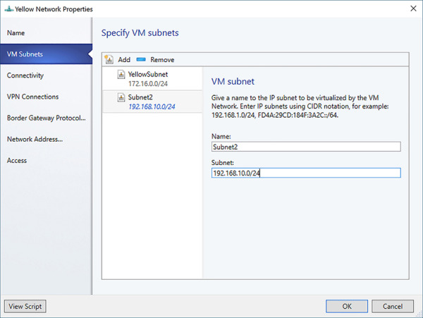
FIGURE 2-34 Configure VM subnets for a VM network
)
)
)
)
 QUICK CHECK
You are planning connectivity of an on-premises network to a SDN deployment. How will local routes be advertised to the cloud environment?
Quick check answer
SDN uses BGP peering to exchange routing information for VIPs and tunnels. The transit network is used to distribute routes across the SDN roles in the fabric.